Processes occurring in the ground, for example, frost heaving, stretch the tape monolithic foundation in different directions. Concrete without reinforcement does not withstand such loads, since it extends without a rupture only by 0.2-0.4 mm. Steel stretches to 4-25 mm without damage, so the reinforced concrete structure is much stronger. For the qualitative work of this system it is important to calculate the circuit and correctly execute the reinforcement. You can do it yourself, most importantly - do not violate the requirements of the instruction.
1. Draw the drawing.
Prior to the calculation of materials, a scheme is drawn up that corresponds to the building codes. The reinforcement for the foundation is divided into working and structural. The first group works on stretching, and the second retains the shape of the frame during pouring.
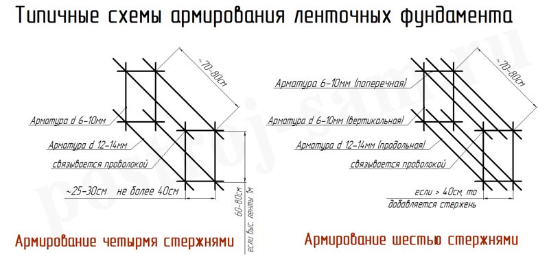
For a shallow basin foundation, two rows of longitudinal reinforcement bars are sufficient at the top and bottom, in the middle they are inserted for strength when concreting. The recessed ribbon is reinforced evenly, the maximum distance between the longitudinal rods is 40 cm. In both cases, the main role of vertical reinforcement is the support of the carcass, therefore rods with a smaller diameter are chosen for it. If the height of the tape of a two-story house is more than 70 cm, for the strength, bind the concrete preparation and foundation.
Minimum distance between elements:
- Between vertical bars - no more than 50 cm.
- The protective layer of concrete is 3-5 cm if there is concrete preparation under the base; 7 cm when it is not.
- The distance between the longitudinal reinforcement is not less than 3-6 cm, depending on the number of rods in the row, and not more than 20 cm.
Angles and joints of the outer and inner bands are experiencing heavy loads. Carefully study the drawings and schemes for reinforcing the ribbon foundation. For angles, P and L-shaped schemes are used. To fulfill them, the rods are pre-bent, since the knitting of individual elements in these places leads to delamination of concrete and chips. Transverse reinforcement in such zones is put in 2 times more often.
2. Choose and calculate materials.
The most commonly used class A-III (A400-A500) ribbed reinforcement with a diameter of 6-16 mm, because it better grips with concrete. For vertical clamps in ribbon foundation sometimes take a smooth A-I-A-II. The diameter depends on the weight and structure of the foundation, below are the minimum cross-sectional dimensions for each target. If you are making a scheme for reinforcing a heavy structure, instruct the execution of calculations to the designers. Correctly calculate the load and choose optimal diameter and the number of rods themselves is difficult.
3. Clean the surface of the base from excess debris, mark the location of the frame.
4. Flex the rods for clamps and corners.
There is no single sequence of reinforcement laying, the choice depends on the area and the number of workers. For small grounds, the elements are first connected, and then they are placed by parts into the trench. But it is difficult to install the frame in-house, especially if it is necessary to reinforce the large-area strip foundation. Therefore, further we will disassemble the stacking order, which is often used by small construction brigades.
5. Install the clamps on concrete supports or fixatives-frogs. To ensure that the frame does not move, a tightly roped rope is passed through it, or each element is tied to the formwork.
6. In the design insert longitudinal rods and fix them on the frogs.

7. Corner reinforcement is performed if additional elements are used for this.
8. Knit or solder the entire structure. For more information on how to connect, see the recommendations section.
9. Install the locks between the walls of the formwork and the reinforcement.
10. Check the strength and deviations from the axes so that the ribbon foundation does not squint with time.

Nuances of works
1. Calculation of reinforcement materials.
Provide that the reinforcement is sufficient for the overlap (30-50 mm). The standard length of the rod is 11.7 m. Do not order trimming, as the laboriousness of the work will increase, and it will be impossible to calculate the necessary quantity, because the reinforcement is sold in kilograms.
2. Connection.
The cores are soldered, knitted or clamped together. It is better to knit reinforcement elements rather than braze, as the strength of the frame falls, especially if left without concrete in wet weather. To reduce the consumption of reinforcement for the strip foundation, couplings are used, since it is recommended to connect the rods with an overlap of 10-15 cm, for soldering, depending on the diameter. If they are knit, the length of the bonding site is 10 diameters for concrete grades from M300 and 15 for M200.
You can knit with a hook, a special pistol and a screwdriver or a drill with a nail attachment. PROCESS The reinforcement of the belt base with hand crocheting takes a long time.
3. Bending of rods.
On sale there are machines to bend the reinforcement, but they are expensive, so the craftsmen came up with different ways for making yokes themselves. For example, weld two corners to a flat vertical surface, insert a rod and bend there, putting a pipe on it. The reinforcement with a diameter of 6-8 mm is used to grind the vice. If you have the wit, to realize the idea with two parallel corners will be easy. The main thing is that all corners are straight, and the sides of the yokes are in the same plane, otherwise ribbon base will not be reliable.
4. Preparation of reinforcement elements.
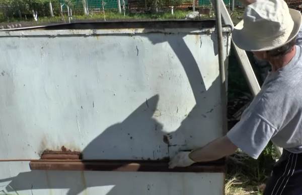
Rods are slightly soaked a couple of days before pouring, to increase the adhesion of steel to concrete, but before doing so, remove the rust peeling off with a metal brush.
Possible mistakes
When people without experience reinforce the construction with their own hands, often they do not look at the leadership and make typical miscalculations, this leads to a sad result.
| Error | Why not |
| Heat the rods before folding. | Reinforcement turns out to be fragile. |
| To solder valves without the letter "C". | The frame will not withstand high temperatures and breaks faster. |
| Insert the transverse reinforcement into the sand and soil pillow. | Steel quickly rusts in this position. |
| Use in the reinforcement of some trimming. | The frame will not function. The maximum proportion of connections in the structure is 50%. |
| Connect parallel rods without running out. | Such an armature will not work. The minimum length between the fastenings of adjacent rods is 61 cm. |
| Do not bend at the corners. | Concrete will quickly peel off from these places, since the load on them is higher. |
| Fill curve armocome. | Belt foundation also eventually rustles. |
For reinforced concrete to work, it is necessary to perform reinforcement monolithic foundation correctly drawn up drawing. This is important for a shallow, shallow basin, as it is in the zone of constant soil movement.
If you do the self-reinforcement, carefully follow the instructions, even if you are assisted by specially hired workers. Monitor the process, because sometimes companies hire people who do not know the basic standards of construction or just shuffle.
Mankind has accumulated vast experience of construction during its entire existence. The basis, the base of any structure is a solid and reliable foundation. Today, the most common type of foundation is a building permit, because it is this one that evenly distributes the weight of buildings to the ground, which in turn affects the process of shrinking the house. A reinforcement of the belt foundation is the way to make the foundation of the structure stronger and more reliable.
Steel and concrete are the main carriers construction Materials. The properties of the materials are different. Comparison table of properties of some materials:
As we see, steel is much stronger and more reliable than concrete, but at the same time, concrete is 80 times cheaper than steel. Therefore, the composite material appeared reinforced concrete. Since concrete works well for compression, the location of steel in reinforced concrete structures - in places subject to stretching and bending.
Many believe that the foundation only works to compress and reinforce the ribbon foundation - money thrown to the wind. This is correct if the foundation is placed on rocky grounds. But in most cases, the soil is not a solid monolith. There are many factors that cause the base to work on bending:
- Heterogeneity of the soil. Different density of layers leads to uneven shrinkage.
- Soil erosion by atmospheric precipitation or groundwater.
- Mobility of surface layers of soil.
- Frosty whipping. The close location of groundwater and the negative temperature causes clay soils to increase in size by 10-15% (swelling). In this case, the base begins to push the foundation upwards.
As a result, there is a stress in the concrete structures that destroys the material. Cracks and shrinkage of the foundation lead to the formation of cracks in the walls of the house, which spoils the appearance of the structure or to its collapse. In other words, it is more expensive to save on reinforcing the foundation, because repairing and rebuilding a house requires tangible monetary costs.
The technology of reinforcement is the process of creating a spatial reinforcement skeleton. It consists of the following elements:
- longitudinal reinforcement;
- transverse;
- vertical;
- strengthening clamps;
- knitting wire.
The longitudinal reinforcement fits along the long side of the basement, and the length of the rod usually reaches 6 or 12 m. It is precisely this that resists stretching. Longitudinal reinforcement is performed along the upper and lower edges of the reinforced concrete structure.
The laying scheme depends on the calculation of the required cross-sectional area of the reinforcement. Such a calculation requires careful consideration of all loads on the foundation, including climatic conditions from snow and wind, as well as the weight of the foundation itself. The carrying capacity of the soil is taken into account in geological studies (geological cross-section). In GOST 5781-82, Table 1 contains the cross-sectional area for each rod diameter, it remains to be decided how many rods to place on the top and bottom side of the foundation.
However, for those who decided to build a house independently with their own hands, you can do without calculations using the recommendations of paragraph 10 and section 5 of the manual "On the design of concrete and reinforced concrete structures from heavy concrete without prestressing the reinforcement". They indicate that the minimum cross-sectional area of the reinforcement is As = μ * b * ho, where:
As is the cross-sectional area of the reinforcement;
μ = 0,1% - percentage ratio for bent structures;
b is the width of the section of the strip foundation;
ho - height working area section (equal to half the height of the section of the foundation).
The diameter of the upper rods can be equal to the diameter of the lower ones or smaller. The maximum distance between the axes of the longitudinal rods (step) is recommended to take no more than 1,5h or not more than 400 mm in the beams and plates, where h\u003e 150 mm - the height of the cross-section of the foundation (clause 10.3.8 of the JV and clause 5.13 of the Manual). Only in this case is the efficient work of concrete and reinforcement ensured, and the width of the crack opening between the longitudinal rods is limited.
The minimum pitch of the rods (the distance between the axles) is limited for convenience of laying and compacting the concrete mixture and is equal to:
- d + 25 mm - for the lower reinforcement series;
- d + 30 mm for the upper one.
Let's consider an example:
It is necessary to reinforce the basement of a width of 400 mm, 600 mm high. It is necessary to calculate how many rods and diameters will be needed. The minimum sectional area of the reinforcement is: Аs = 40х30х0,1% = 1,2 cm². The distance between the rods is 1,5x600 = 900 mm, therefore, we take no more than 400 mm. That is, the width of the cross-section is set to 2 bars. We select the diameter of the reinforcement in accordance with GOST 5781-82 table 1: two bars Ø 8 mm have an area Аs = 2х0,503 = 1,006 cm², which is less than the required 1,2 cm². Consider the following diameter Ø 10 mm. As = 2х0.785 = 1.57 cm2. As a result, the layout of the rods looks as follows: take the upper and lower armature equal to Ø 10 mm and lay it in two rows.
Many builders today use the following rules to select the diameter of the rods: the diameter must be at least 10 mm if the side of the foundation is less than or equal to 3 m and 12 mm for the side more than 3 m (see the Reference "Reinforcement of the elements of monolithic reinforced concrete buildings" Appendix 1). However, the rules of the manual are designed for the design of monolithic reinforced concrete structures of multi-storey houses, taking into account emergency loads and progressive collapse. Of course, those who build a house with their own hands, the safety factor will not hurt, but it's no longer a question of a reasonable expenditure of reinforcement.
When reinforcing, do not forget about the protective concrete layer - the distance between the side surface of the basement and the core of the reinforcement. A protective layer is necessary for several reasons: it protects steel from the corrosive effects of air and groundwater. In addition, for normal operation of reinforced concrete, the reinforcement must be inside the concrete. The minimum value of the layer depends on the operating conditions of the structure and for structures located in the ground, foundations with a device concrete preparation is equal to 40 mm and not less than the diameter of the working armature (Table 10.1 SP and Table 5.1 of the Manual).
More details about the calculation of fittings.
Transverse structural reinforcement
Under the structural transverse reinforcement is meant horizontal and vertical rods, which:
- Support longitudinal reinforcement in the design working position.
- Prevent the development of cracks.
- They perceive unaccounted load, for example, lateral buckling of the foundation.
The diameter of the transverse reinforcement in the knitted bent frames is at least 6 mm. In Appendix 1 of the Manual "Reinforcing the elements of monolithic reinforced concrete buildings", the transverse reinforcement is recommended to be made in the form of a closed yoke with a core diameter of at least 8 mm.
Tool for bending of clamps of reinforcement.
The distance between the rods (step) is taken no more than twice the width of the cross section and not less than 600 mm. With regard to the protective layer, the minimum distance between the core and the concrete edge is 5 mm smaller than the minimum layer size for the longitudinal reinforcement, that is 35 mm.
Materials used
Materials for reinforcement are accepted in accordance with GOST 5781-82. The armature is made of low-alloy and carbon steel in accordance with GOST 380-2015. The surface of the rods can be smooth or periodic. Depending on the properties of the material is divided into the following classes:
- A 240 (A-I);
- A 300 (A-II);
- A 400 (A-III);
- A 600 (A-IV);
- A 800 (A-V);
- A 1000 (A-VI).
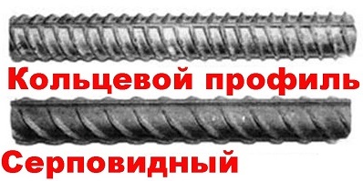
For the foundation you need a reinforcement with a sickle-shaped profile.
The numerical code reflects the yield strength, for example, 240 corresponds to 235 N / mm². Among them, only A 240 (A-I) is made of a smooth profile. In the range of products are limited to a diameter of 6 to 40 mm.
Skeletons can be welded or tied. For bonding and reinforcement, low-carbon steel wire of GOST 6727-80 round ( make B-I) or ribbed (grade Bp-I), with a diameter of 3.0; 4.0.
Tip: The best solution the foundation will be reinforcement brand A400 (AIII), the use of higher grades is not justified, because without prestressing its strength potential will not be used 100%.
It should be noted that in recent years in the construction industry there was a composite reinforcement of fiberglass. The material is durable and lightweight. The material has many advantages: easy installation technology, has high anti-corrosion properties.
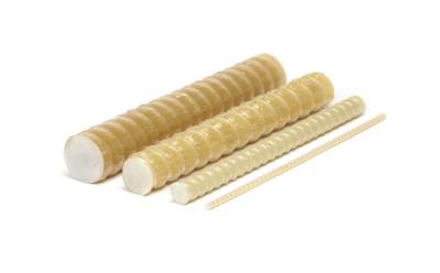
Photo of composite reinforcement.
However, there are also drawbacks to the material. It has self-extinguishing characteristics during combustion, but at a temperature of 200 ° C it loses its properties. In addition, it is badly bent, which makes it difficult to use curved elements. Many professional builders refused to work with this material due to lack of practical experience (foreign experience was not taken into account) and recommendations on the calculation.
But from July 2015, in the joint venture 63.13330.2012, Appendix L appeared with the rules for constructing and calculating structures. For those who prefer to build themselves, there are design requirements for reinforcement.
Rules for reinforcing corners and contiguities
Often on the construction site the reinforcement has to be carried out from the residues, so the rods are overlapped, welded or special butt joints are used. When splicing is overlapped, the ends of the smooth-profile armature are bent in the form of legs, hooks and loops, and the ends with a periodic profile can not be bent. The distance between the connecting bars can be from zero to 4 diameters of the reinforcement. The joint length is calculated according to the design manual, but can not be less than 15 rod diameters or 200 mm.
Butt welded joints are made with the help of staples, and in the mechanical joints, threaded and crimp clutches are used.
Important! The rules prohibit the reinforcement of corners by a simple overlap, since in this case the angle will not be complete and fixed.
Angle and T-shaped abutments of frames are produced in three ways: paws, additional curved bands of the G and P forms.
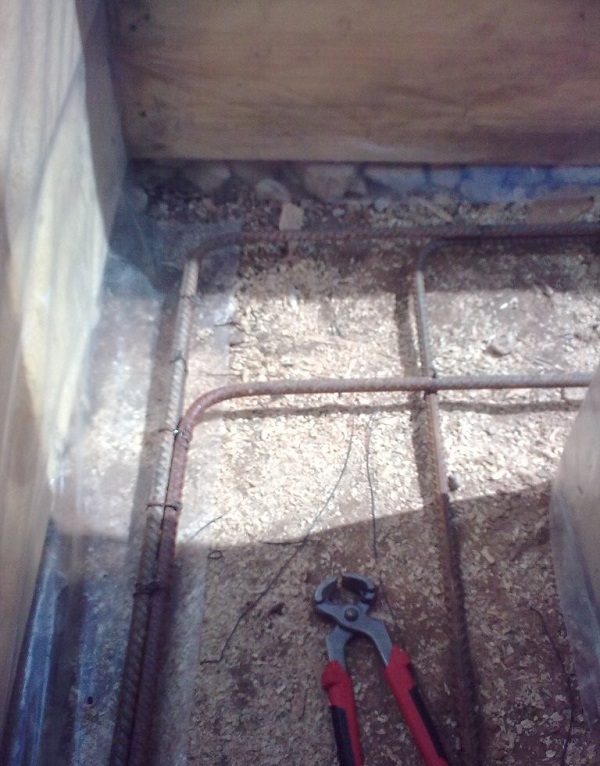
Photo how to properly reinforce the angle.
More details about the reinforcement of corners.
Knitting fittings
It would Seem, welded skeletons to use faster and more conveniently. Nevertheless, builders prefer to knit spatial frameworks. And there are reasons for this:
- Welding reduces the quality of the metal.
- The sedimentation of the soil during the production of foundations provokes additional stresses at the joints. Welding connections do not always cope with loads and are destroyed. The associated details do not change the position in space, but they have a certain mobility.
Advice! If you need contractors, there is a very convenient service for their selection. Just send in the form below detailed description works that need to be done and to you on the mail will come offers with prices from construction teams and firms. You can see reviews about each of them and photos with examples of works. It is FREE and does not bind you to anything.
The owner who is going to build a house must have at least some performance, where to begin construction.
And most importantly, is necessary know where to start and how.
Capital houses must stand on lasting A foundation that can last for decades and withstand all the stresses.
Reinforcement - is the laying of rods of strong steel along the foundation tape. Concrete stone has large indicators strength In the case of compression, but with a load on the fractures, it is not so strong.
Different soil structures and building features can cause uneven load, which leads to various deformations, including ruptures.
As a result of ruptures, the foundation can be covered cracks. And any of them can lead to the destruction of the house.
To strengthen the design and compensate for this shortcoming, reinforce the base of the tape type. Steel reinforcement, which is placed inside concrete, helps Eliminate its stretching, making it durable and sustainable to temperature differences and heavy weight.
What kind of fittings should I use?
For a framework, the following types of fittings:
- rods Steel A-III, the diameter of which 1,0-1,6 cm, and the length of about 600 cm;
- clamps, whose diameter 0,5 -1 cm, they are made from auxiliary fittings Вр-І;
- vertical rod-pins diameter 1 cm.
Use auxiliary reinforcement be sureif the foundation is reinforced with a height of more than 15 see Vertical rods are designed to connect the vertical parts of its structure and uniform distribution of loads along the entire foundation of the structure.
Valve calculation
When calculating the reinforcement of a strip foundation, take into account such parameters:
on the links of the framework of the armature;The maximum load is accounted for by longitudinal parts skeleton. because optimal option will be the use of ribbed pins for wireframe. Thanks to this, the quality adhesion to concrete.
The laying of the frame is carried out taking into account the difference in the parameters of the soil. The more it is, the more thicker The bars of the reinforcement must be used in the frame.
Steel rods laid along the perimeter of the foundation should be located at a distance more 50 mm from the upper edge of the base, formwork and bottom. The reinforcement placed in the concrete must receive corrosion protection.
The distance between the rods is determined, for example, as follows. Let the width of the base be 0,4 m, then distance between the rods, located along, should be equally:
- 1-3 dm in vertical depending on depth and load;
- 3 dm horizontally.
Smooth rods that withstand less loads are used for vertical and the transverse elements of the frame. They are located at a distance 1-3 dm from each other. Sometimes it is possible to have rods at a distance up to 5 dm.
To increase the strength of a monolithic concrete strip foundation, as a rule, it is reinforced with steel reinforcement. But those who for the first time build a foundation of this type do not always know how to properly tape the foundation with their own hands. Therefore, we hope that the information presented in this article will be useful for those who want to know how to do it correctly.
Reinforcing framework for the ribbon foundation
Concrete is quite strong, but not enough plastic material. It copes well with compression loads, but it can break down under tensile loads. Therefore, to increase the stability and reliability ribbon foundation it must be strengthened. The most common method is to reinforce the ribbon foundation with the help of a reinforcing cage, which is a steel reinforcement laid in a certain pattern and fastened to a rigid structure (frame). The diameter and number of reinforcing bars in each particular case is determined by the calculation.
Calculation of the number of reinforcement and its diameter
 Calculation of the reinforcement for the strip foundation is necessary in order to know how much of which reinforcement and what diameter is needed to give this base sufficient strength. The reinforcement for the strip foundation is used in different types and thicknesses.
When constructing a strip foundation under a private house, as a longitudinal, as a rule, use ribbed reinforcement with a diameter of 10-20 mm. As a transverse and vertical (or for the manufacture of clamps), most often, choose a ribbed or smooth reinforcement of circular cross-section with a diameter of 6-12 mm.
In order to choose the correct reinforcement scheme, it is necessary to determine what minimum reinforcement content should be in the strip foundation, the number of longitudinal rods and the minimum diameter thereof.
The minimum content of reinforcement in the strip foundation
The minimum content of longitudinal reinforcement in any ribbon foundations, according to clause 7.3.5 of SNiP 52-01-2003 "Concrete and reinforced concrete structures", should be not less than 0.1% of the area of the section of the tape. For example, for a basement that has a height of 1200 mm and a width of 400 mm, the minimum total cross-sectional area of the reinforcement should be 480 mm2.
Number of longitudinal reinforcement rods
The total area of the minimum cross-section is divided by the cross-section of the selected reinforcement (3.14 D / 4), and the required number of longitudinal rods is formed to form the frame, rounding their number to a larger side.
In addition, knowing the total minimum cross-section of the reinforcement, you can choose the number of rods of a certain diameter according to Table 1:
Table 1. The total area of the reinforcement, depending on the diameter and number of rods, mm 2.
|
Number |
rods |
||||||||
|
Diameter, mm |
|||||||||
The minimum diameter of the reinforcement for the ribbon foundation
In addition to the minimum sectional area of the reinforcement, depending on the specific conditions of its use, it is necessary to determine and with the minimum permissible diameter of its rods. You can use the data shown in Table 2:
Table 2. The minimum allowable diameters of reinforcement when reinforcing the basement.
| Conditions for the use of fittings |
Minimum allowable diameter of rods, mm |
Normative document |
|
Longitudinal reinforcement along side not longer than 3 m |
Appendix 1 to the Manual "Reinforcement of elements of monolithic reinforced concrete buildings»M., 2007 |
|
|
Longitudinal reinforcement along side longer than 3 m |
||
|
Transverse reinforcement (yokes) of knitted skeletons with a height not exceeding 80 cm |
item 3.106 Guidelines for the Construction of Concrete and Reinforced Concrete Structures from Heavy Concrete (without pre-stress) M., 1978 |
|
|
Cross reinforcement of knitted skeletons with a height of more than 80 cm |
Calculation of the required number of valves
The necessary number of reinforcing bars for reinforcing the strip foundation can be determined by measuring or calculating the length of its tape and multiplying by the number of longitudinal rods in all tiers.
After that it is necessary to calculate the required amount of transverse reinforcement. To do this, calculate the number of clamps to be installed (the length of the tape is divided by the distance between the clamps) and multiplied by the length of the rod that will be required for making one clamp. Also we act, if not the clamps, but the pieces of the armature, are used as the transverse.
After the required number and cross-section of the bars of the longitudinal reinforcement for the future belt foundation have been calculated and selected, it is necessary to choose the reinforcement scheme, according to which the skeleton will be knitted.
The scheme for reinforcing the belt foundation can be different, but in any case, it is necessary to choose one that would be the most simple and sufficiently reliable. Sometimes a scheme is chosen in which only the lower or only the upper part of the basement is reinforced. This is not entirely correct.
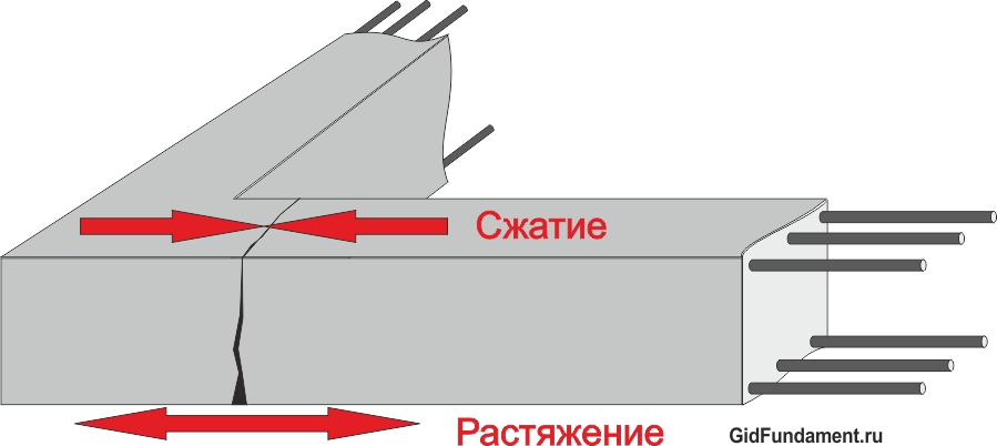
Since, on the one hand, the weight of the house will act on the tape. It should be taken into account that the resistance of concrete to compression is much greater than its tensile strength, which can be caused at the bottom of the tape. On the other hand, the forces of frost heaving of the soil can cause tension tension at the top of the basement. Therefore, it is necessary to reinforce the upper and lower parts of the foundation.
To produce the same reinforcement of the middle part of the band foundation is not necessary, since it practically does not experience tensile stresses. Although, if the calculated amount of reinforcement is such that it does not fit in two rows (upper and lower), it is quite possible to device additional stages in the middle of the frame.
Best of all, if the reinforcement scheme of a monolithic basement for the foundation will consist of simple geometric shapes (square, rectangle). In this case, the axes of the carcass are easiest to make right, and the foundation itself will be strong.
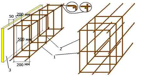
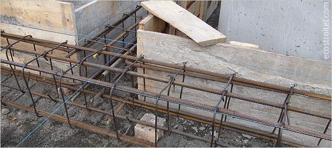
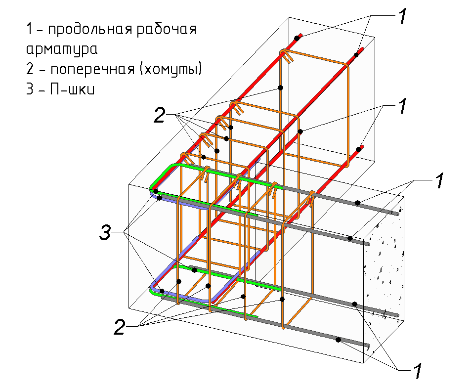
Fig.1 Variants of ribbon foundation reinforcement schemes: 1 - longitudinal reinforcement; 2 - vertical reinforcement (yoke); 3 - formwork ; 4 - transverse reinforcement (yoke).
Particular attention should be paid to the correct choice of the installation schemes for the fittings at the corners and in the areas where the walls meet. Below are diagrams of reinforcement, using which you can correctly connect the reinforcement frame in these places.
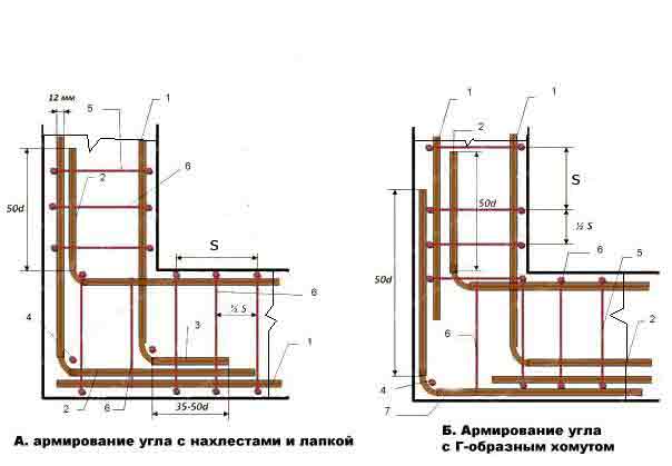
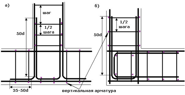
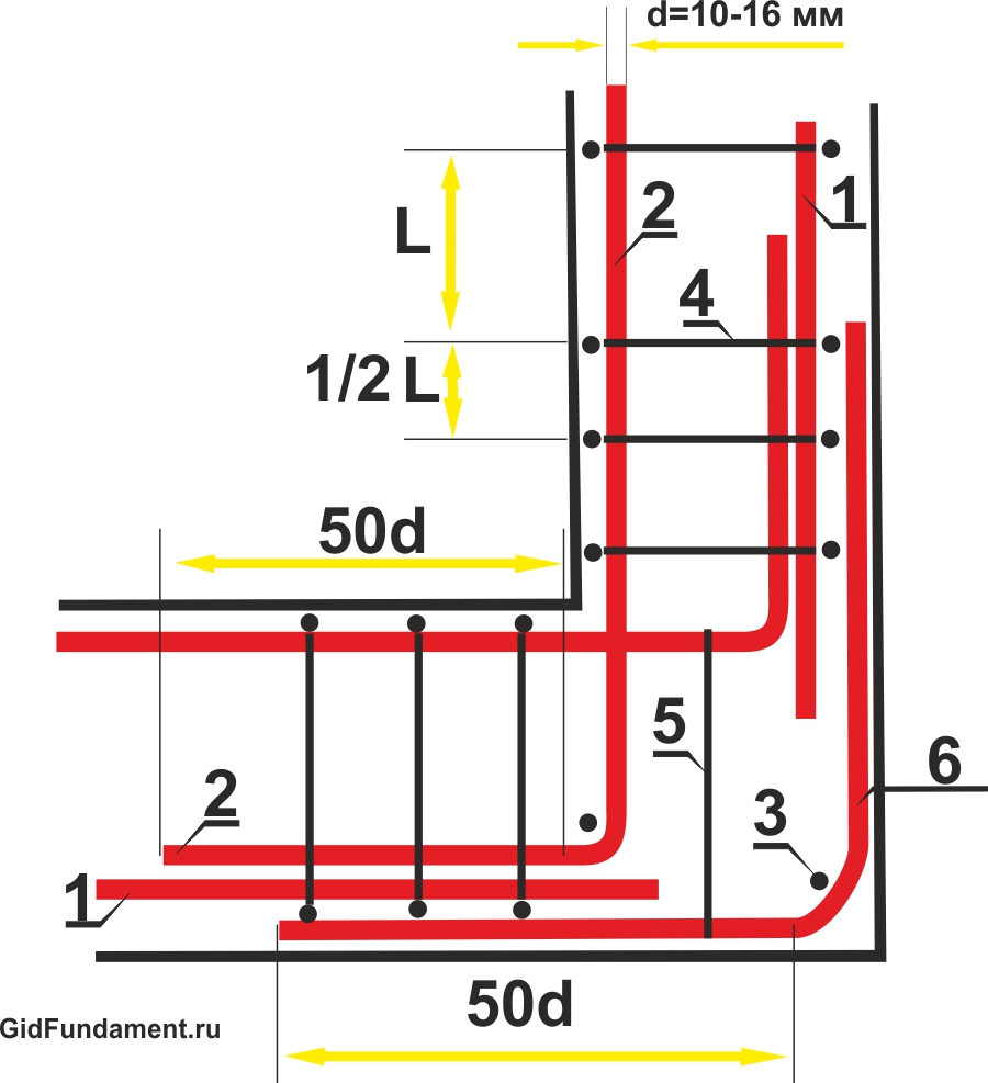
Fig.2 Scheme reinforcing the corners of the ribbon foundation: 1 - longitudinal horizontal reinforcement; 2 - overlap; 3 - connecting tab 90 о; 4 - vertical reinforcement (yoke); 5 - transverse reinforcement (yoke); 6 - additional transverse reinforcement; 7 - L-shaped clamp; d - diameter of reinforcement, mm; Distance S should not be more than 1/2 the height of the frame.
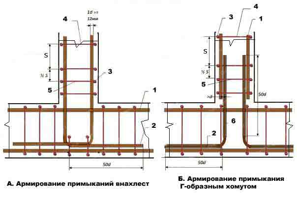
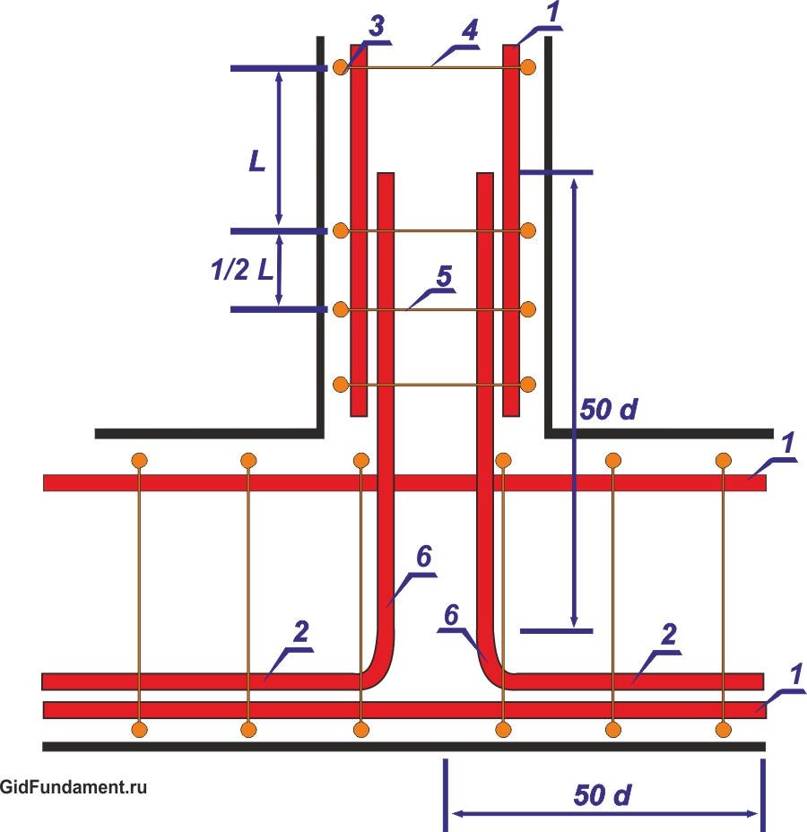
Fig. 3 Scheme of reinforcement of abutments of the belt foundation: 1 - longitudinal horizontal reinforcement; 2 - overlap; 3 - vertical reinforcement (or clamp); 4 - transverse reinforcement; 5 - additional reinforcement; 6 - L-shaped clamp; S - no more than 1/2 of the height of the frame; d is the diameter of the reinforcement, mm.
Carrying out of works on installation of a skeleton
Before installing the frame from the reinforcement, it is desirable to make a concrete base - a sand and gravel pillow in the basement foundation, pour concrete with a layer of 5-8 mm and allow it to grasp. If there is no desire to do the concrete, then under the lower row (tier) of the reinforcement, it is necessary to install supports so that between the cushion and the armature there is a gap of 5 cm for penetration of concrete and protection of the reinforcement from below.
For the device of horizontal rows (tiers), the most commonly used round ridge armature of class A ||| with a diameter of 10 -16 mm. The longitudinal bars are joined by a horizontal transverse reinforcement. Between themselves, the bars of the longitudinal reinforcement are connected with an overlap of not less than 50 diameters of the reinforcement in cm (50d).
With a foundation ribbon height of more than 0.15 m, the upper and lower tiers, it is desirable to connect also vertical reinforcement. More often, for this purpose a smooth reinforcement of class A | with a diameter of 6-8 mm. It is best to use as a transverse and vertical reinforcement clamps from this armature, curved in the form of a frame, which are made to the size of the frame.
In addition, no matter what scheme of reinforcing the tape foundation is not chosen, it must be remembered that the distance between reinforcement and formwork, as well as the top level of pouring concrete should not be less than 5 cm, to ensure the presence of a protective layer of concrete.
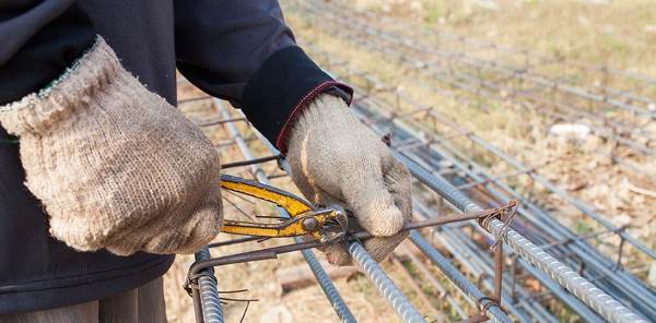
The connection of individual rods to each other during the construction of the frame must be carried out with a soft steel knitting wire. It is best to use a special crochet hook, which you can easily make with your hands from a piece of reinforcement and a wooden or plastic handle.

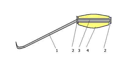
Fig. 4 One of the variants of a self-made hook for binding reinforcement with a binding wire: 1 - a hook from a reinforced reinforcing bar with a diameter of 6-8 mm; 2 - thrust washers (seized by welding); 3 - the core of the handle; 4 - handle with a hole, wooden or from a plastic tube.
The inner hole in the handle should be such that the core together with the hook can rotate freely when binding the wire. The binding wire, curved twice, is wound under the joint of the reinforcement. Sharp end hook hooks the "loop" of the wire and rotational movement (2-3 turns) connects it to its other end (double). In this case, do not overdo it so as not to "cut off" the wire at the binding site.
Weld the frame is not desirable, and if you do this, then only from the armature that allows welding (which has the letter C in its marking).
When forming the frame, it is necessary to try to ensure that the diameter of the reinforcement for the strip foundation (longitudinal rods) is the same size and placed evenly along the width of the tape. If it so happens that you have to use reinforcement of different diameters, then the rods of a larger diameter should be placed in the lower part of the tape, at the corners and at the points of the kinking of the yokes.
When reinforcing the belt foundation, it should also be taken into account that it is not possible to place the reinforcing bars of the upper row of the frame above the gaps between the bars of the lower armature. In this case, the diameter of the longitudinal reinforcement should not be less than the diameter of the transverse rods, as in the case of bonding the frame with a knitting wire, and when welding it.
Reinforcing the base of the video
Any building, regardless of its purpose, is unthinkable without a reliable foundation. The erection of the foundation is one of the most important and natural tasks of the entire construction cycle as a whole, and this stage, by the way, is often one of the most labor-consuming and costly - quite often up to a third of the estimate goes to it. But at the same time, there should be absolutely eliminated any simplifications, unreasonable savings in quality and quantity necessary materials, neglect of existing rules and technological recommendations.
Of all the diversity of foundation structures, the most popular tape belt, as the most universal, is suitable for most houses and farm buildings being built in the field of private construction. Such a base is distinguished by high reliability, but, naturally, with its high-quality execution. A key condition for strength and durability is a well-planned and properly carried out reinforcement of the tape base, drawings and basic principles of the device which will be considered in this publication.
In the article, in addition to the schemes, several calculators will be presented, which will help the beginning builder in accomplishing this rather difficult task of creating a ribbon foundation.
General concepts. Advantages of the belt foundation
So, briefly, there are several general concepts about the arrangement of the ribbon foundation. In itself, it represents a continuous concrete strip, without any breaks on the door or portal openings, which is the basis for the erection of all external walls and capital internal partitions. The tape itself is buried at a certain design distance into the ground and at the same time protrudes from above with its basement part. The width of the tape and the depth of its laying, as a rule, is maintained uniform throughout the entire length of the basement. This shape promotes the most even distribution of all loads falling on the building base.
Belt foundations can also be subdivided into several varieties. So, they are not only poured from concrete, but also made prefabricated, using for this, for example, special foundation reinforced concrete blocks, or using butovo filling. However, since our article is devoted to reinforcement, in the future only a monolithic version of the foundation tape will be considered.
Tape foundation can be attributed to a universal type of foundation. Such a scheme is usually preferred in the following cases:
- When erecting houses from heavy materials - stone, brick, reinforced concrete, building blocks and the like. In a word, when you want to evenly distribute a very significant load on the ground.
- When the developer plans to get a full cellar or even a basement at his disposal - only a ribbon scheme can afford it.
- When building multi-level buildings, with the use of heavy interfloor overlapping.
- When the site for building is characterized by heterogeneity of the upper layers of the soil. The only exceptions are absolutely non-stable soils, when the creation of the belt foundation becomes impossible or unprofitable, and it makes sense to turn to another scheme. A band foundation is also impossible in regions with permafrost.
Monolithic tape foundation has a lot of other advantages, which include durability, estimated by many tens of years, relative simplicity and understandability of erection, wide possibilities in terms of laying utilities and organization of insulated floors of the ground floor. On its strength properties, it does not concede monolithic plates, and even surpasses them, while demanding less material costs.
However, one should not think that the strip foundation is an absolutely not vulnerable design. All the listed advantages will be valid only in the event that the parameters of the erected basis for the house will meet the conditions of the construction area, the design load, and have a built-in safety reserve. And this, in turn, means that the design of the foundation (any, by the way) is always subject to special requirements. And reinforcing the tape in a series of these problems is one of the key positions.
The width of the foundation tape and the depth of its foundation
These are the two key parameters on which the reinforcement scheme of the future foundation tape will depend.
But the degree of penetration into the ground belt foundations can be divided into two main categories:
- A shallow strip foundation is suitable for the construction of frame structures, small country houses and outbuildings, provided a fairly stable, dense soil on the site. The sole of the tape is located above the freezing point of the ground, that is, it usually does not drop below 500 mm without considering the basement part.
- For buildings constructed from heavy materials, as well as in areas where the condition of the soil is not stable, a deep-seated tape is required. Its sole is already lowered below the freezing level of the ground, at least 300 ÷ 400 mm, and if there are also basements (basement) in the construction plans, it is even lower.
It is clear that the height of the foundation tape as a whole, including the depth of its bedding, is by no means arbitrary, but parameters that are obtained as a result of carefully performed calculations. The design takes into account the whole array of initial data: the type of soils on the site, the degree of their stability both in the surface layers, and the change in structure as it deepens; climatic features of the region; presence, location and other features of groundwater aquifers; seismic characteristics of the area. In addition, the specificity of the building planned for the erection is superimposed - the total load, as static, created only by the mass of the structure (naturally, taking into account all its constituent elements), and dynamic, caused by operational loads, and all kinds of external influences, including wind, snow and others.
Proceeding from the above, it is appropriate to make one important observation. The principal position of the author of these lines is that the calculation basic parameters foundation tape - does not tolerate the dilettante approach.
Despite the fact that on the Internet you can find many online applications for such calculations, the question of designing the foundation will still be more properly entrusted to specialists. At the same time, the correctness of the proposed calculation programs is not in the least disputed - many of them fully comply with the current SNiP and are able to really give accurate results. The problem lies in a slightly different plane.
The bottom line is that any, even the most perfect calculation program, requires the input of accurate initial data. But in this matter, without special preparation, it is impossible to manage. Agree that it is correct to assess the geological features of the site for construction, take into account all the loads falling on the foundation tape, and - with their decomposition along the axes, to provide for all possible dynamic changes - the layman simply can not. But every initial parameter has a value, and underestimation of it can well then "play a cruel joke."
True, if it is planned to erect a small country house or an economic building, the invitation of a specialist-designer may seem like an excessive measure. Well, at your own peril and risk, the owner can erect a shallow ribbon foundation, using, for example, the approximate parameters that are given in the table below. For light buildings, a heavily recessed tape is not required (great burial can play even a negative role, due to the application of tangential forces in the case of frosty swelling of the soil). As a rule, in such cases, the maximum depth of the sole is 500 mm.
| Type of erected building | Shed, sauna, outbuildings, small garage | One-storey country house, including - with a penthouse | One- or two-storey cottage, designed for permanent residence | Two or three-story mansion |
|---|---|---|---|---|
| Average load on the ground, kN / m² | 20 | 30 | 50 | 70 |
| TYPES OF SOILS | RECOMMENDED DEPTH | TAPE INSTALLATIONS | (WITHOUT ACCOUNTING OF THE CORRECTNESS | PARTS OF THE FOUNDATION) |
| Extremely stony ground, flask | 200 | 300 | 500 | 650 |
| Dense clay, loam, not decomposing after compression by palm force | 300 | 350 | 600 | 850 |
| Dry sand, sandy loam | 400 | 600 | Required professional foundation calculation | |
| Soft sand, silt or sandy loam | 450 | 650 | Required professional foundation calculation | Required professional foundation calculation |
| Very soft sand, silty soil or sandy loam | 650 | 850 | Required professional foundation calculation | Required professional foundation calculation |
| Peatbog | A different type of foundation is required | A different type of foundation is required | A different type of foundation is required |
Once again, we emphasize-these are only averaged values that can not be regarded as true in the last instance. In any case, if an amateur builder uses such sources, he assumes a certain risk on his own responsibility.
Now - about the width of the foundation tape.
There are also features here. First, to ensure the rigidity of the foundation construction, it is customary to adhere to the rule that the total height of the tape should at least double its width - but this rule is easy to observe. And the second - the width of the tape in the area of the sole should be such that distributed load was less than the calculated parameters of soil resistance, of course, also with a certain constructive reserve. In a word, the foundation tape with full load should stand stably, not sinking into the ground. In order to save materials, often to increase the footing area, the sole of the belt foundation is made with a broadening.
Probably, it makes no sense to give here formulas and table values of soil resistance for carrying out independent calculations. The reason is the same: not so much the difficulty in performing calculations, how many problems with the correct definition of the original parameters. That is, again, it is better to turn to professionals in such matters.
Well, if you are building a light structure or a summer cottage, you can be guided by the fact that the width of the tape should be at least 100 mm larger than the thickness of the walls being erected. As a rule, with independent planning of the foundation take round values, multiples of 100 mm, usually starting from 300 mm and above.
Reinforcement of the foundation tape
If a specialist is engaged in designing the belt foundation, the finished drawing will undoubtedly include not only the linear parameters of the concrete belt itself, but also the reinforcement characteristics - the diameter of the reinforcing bars, their number and spatial arrangement. But in the event that a decision is made to construct the base for the building independently, when planning the design it is necessary to take into account certain rules established by the current SNiP.
Which fittings are suitable for these purposes?
For proper planning, you need at least a little understanding of the assortment of reinforcement.
There are several criteria for the classification of reinforcement. These include:
- Production technology. So, the armature can be wire (cold-rolled) and rod (hot-rolled).
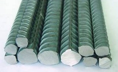
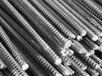
- By type of surface reinforcing bars differ by smooth and having a periodic profile (corrugation). The profile surface of the reinforcement provides maximum contact with the poured concrete.
- The reinforcement can be designed for conventional or prestressing reinforced concrete structures.
To create a reinforcing structure of a strip foundation, as a rule, use the armature manufactured in accordance with GOST 5781. This standard includes hot-rolled products intended for reinforcing conventional and pre-dressed structures.
In turn, this armature is divided into classes, from A-I to A-VI. The difference is mainly in the grades used for the production of steel and, consequently, in the physical and mechanical properties of the products. If low-carbon steel is used in the fittings of primary classes, then in high-grade products the metal parameters approach the alloyed steels.
All the characteristics of the valve classes are not necessary for independent construction. And the most important indicators that will affect the creation of reinforcing cage - are listed in the table. The first column shows the valve classes according to two designation standards. So, in brackets the designation of classes is given, the numerical designation of which indicates the yield strength of steel used for the production of steel reinforcement - when purchasing material in the price list, there may be such indicators.
| Class of reinforcement in accordance with GOST 5781 | steel grade | Diameters of rods, mm | The permissible bending angle in the cold state and the minimum curvature radius for bending (d is the diameter of the rod, D is the diameter of the mandrel for bending) |
|---|---|---|---|
| A-I (A240) | St3kp, St3sp, St3pc | 6 ÷ 40 | 180º; D = d |
| A-II (A300) | St5sp, St5ps | 10 ÷ 40 | 180º; D = 3d |
| -"- | 18G2S | 40 ÷ 80 | 180º; D = 3d |
| AC-II (AC300) | 10GT | 10 ÷ 32 | 180º; D = d |
| A-III (A400) | 35ГС, 25Г2С | 6 ÷ 40 | 90 °; D = 3d |
| -"- | 32G2Ppc | 6 ÷ 22 | 90 °; D = 3d |
| A-IV (A600) | 80C | 10 ÷ 18 | 45º; D = 5d |
| -"- | 20ХГ2Ц, 20ХГ2Т | 10 ÷ 32 | 45º; D = 5d |
| A-V (A800) | 23Х2Г2Т, 23Х2Г2Ц | 10 ÷ 32 | 45º; D = 5d |
| A-VI (A1000) | 22Х2Г2АЮ, 20Х2Г2СР, 22Х2Г2Р | 10 ÷ 22 | 45º; D = 5d |
Pay attention to the last column, which indicates the allowable bending angles and diameters of curvature. This is important from the point of view that when creating a reinforcing structure, come to make bent elements - clamps, inserts, paws, etc. When manufacturing conductors, mandrels or other bending devices, it is necessary to be guided by these values, as reducing the radius of bending or exceeding the angle can lead to loss of reinforcement of its strength properties.
Rods class A-I are produced in a smooth design. All other classes (with some exceptions, which, however, are more dependent on the individual requirements of the customer) - with a periodic profile.
For the basement in private construction, the best choice would be A-III, at most A-II, 10 mm in diameter and above.
For structural elements of the armopoyas (yokes, bridges) it is convenient to use a smooth rod of class A-I, with a diameter of 6 or 8 mm. The use of reinforcing bars of higher grades is unprofitable, because of its high cost in case of obvious lack of demand in such high physical and technical parameters.
"Classical" scheme for reinforcing the foundation tape. Number of longitudinal rods
To begin with - we will consider the typical scheme of reinforcement of straight sections of the foundation tape.
The basis is a rectangle with mandatory levels of reinforcement from above and from below, made of longitudinal reinforcement (item 1), which are connected to each other by horizontal transverse (pos.2) and vertical reinforcement, thus creating a kind of "box" design. This arrangement of the belts makes it possible to compensate as much as possible for the two main multidirectional forces: from the total load created by the building, and from the frost swelling of the soil. In this case, the central part of the tape is loaded least of all, and if the foundation has a total height of up to 800 mm, then two belts are often enough.
With higher bands, the longitudinal belts are arranged in three or more layers. But, as already mentioned, these foundations rely independently - a rather risky occupation.
The illustration shows the linking of longitudinal rods into a three-dimensional structure using the pieces of reinforcement. Such an approach is quite acceptable, however, it does not differ in convenience. The work will go much faster and better, if in advance on the conductor prepare clamps for the dimensions of the armopoyas, and then tie all the details into a common design.
Pay attention to the illustration on which the arrows show two dimensions: H is the height of the reinforcement belt and K is its width. It should be correctly imagined that this is not the height and width of the tape. The metal parts of the foundation must necessarily be protected from oxygen corrosion by a layer of concrete. According to SNiP, the minimum layer is 10 mm, but for the basement, the optimum will be 50 mm to the edge of the concrete structure. This must be taken into account when planning, and already during the installation to maintain the necessary clearance between the reinforcement and the formwork will help simple devices. So, you can set the desired distance from the bottom of the formwork by placing fragments of bricks or installing special plastic racks under the lower bars.
And the required clearance from the side walls of the formwork can be observed, if you use a special locks, "stars" that are simply worn on reinforcing bars.
Now - denser to the question, how many still need twigs of longitudinal reinforcement, and what diameter they should be.
| The area of application of the valve | The minimum diameter of the valve |
|---|---|
| Longitudinal working fittings on rectilinear sections with a length of no more than 3 meters | 10 mm |
| The same, but with a length of the section exceeding 3 meters | 12 mm |
| Transverse reinforcement and clamps of compressed structural elements. | At least 0.25 of the diameter of the working reinforcement, and at the same time - not less than 6 mm |
| Transverse reinforcement and yokes in the area of bent knitted skeletons | 6 mm |
| Clamps for a ribbon crocheted frame not more than 800 mm high | 6 mm |
| The same, but with a knitting frame height of more than 800 mm | 8 mm |
Well, the number of longitudinal rods required to provide the estimated strength of the foundation tape depends on its dimensions and the diameter of the reinforcement used. In accordance with the current requirements of SNiP, the total cross-sectional area of longitudinal reinforcement rods must be at least 0.1% of the cross-sectional area of the belt. Proceeding from this, it is easy to make the necessary calculation. To make it even easier for the reader to do this, the corresponding calculator is placed below.
If an even value greater than 4 rods is obtained, then the armature is recommended to be divided into three belts, placing the middle center between the upper and lower. If you get an odd number, five or more pieces, then with an unpaired rod, it makes sense to strengthen the lower tier of reinforcement - it is there that the highest bending loads are applied to the foundation tape.
Another rule: the requirements of SNiP established that the distance between adjacent elements of longitudinal reinforcement should not exceed 400 mm.
The binding of the longitudinal reinforcement rods to the volumetric structure is made with the help of harnesses. For their manufacture, a special device is usually built-it can be easily assembled on a workbench or on a separate stand.
The step of installing the clamps is also subject to certain rules. So, it should not be more than ¾ of the height of the foundation tape, and at the same time - do not exceed 500 mm. In the areas of reinforcement - at the corners and adjoining walls, clamps are installed even more often - this will be described below.
If on a straight line there is a need to connect two reinforcement bars located along a single line, then a overlap of at least 50d is made between them (d is the diameter of the reinforcing bar). In the application to the most commonly used diameters, 10 and 12 mm, this overlap will range from 500 to 600 mm. In addition, on this site it is desirable to install an additional clamp.
The connection of the fittings and clamps to a single structure is made by linking with the use of steel galvanized wire.
Even if in personal possession there is welding machine, and the owner himself considers himself sufficiently experienced as a welder, all the same reinforcing construction must be carried out by wire twisting. A poorly welded joint, and even worse, overheating of the reinforcement will lead to a sharp decrease in the strength characteristics of the structure being constructed. No wonder that only specialists of the highest qualification are allowed to weld reinforcing structures in industrial construction. And in addition, it is also necessary to use specialized fittings, in the designation of the class of which there is an index "C" - welding.
On the issues of practical knitting reinforcement cage in this publication will not dwell - this topic deserves a separate consideration.
Reinforcement of complex sections of frame construction
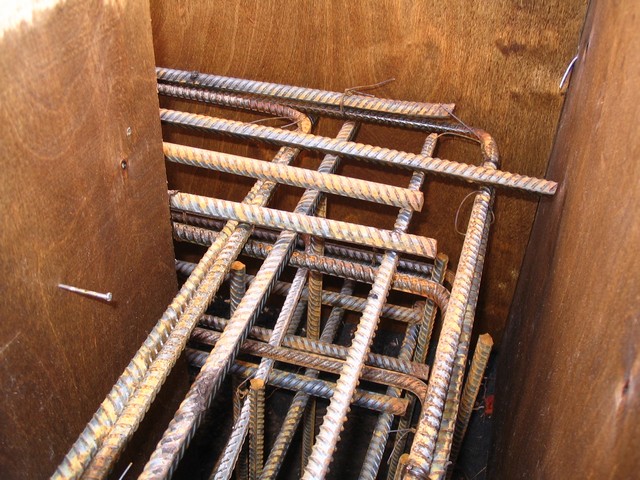
If with the installation of the frame on the straight sections of the reinforcing belt of the belt foundation everything is quite clear, then in difficult areas very often many people make mistakes. Evidence of this - numerous photographs published on the Internet, which clearly shows that two converging frames in the corner or adjacent to each other simply connected by wire twists at the intersection points of the reinforcement.
Incorrectly assembled joints or abutments of reinforcement belts lead to the fact that the uniformity of distribution along the axes of the load falling onto the foundation is violated, which in the future may well result in the appearance of cracks or even the destruction of the tape in these areas. There are certain schemes of reinforcing such nodes - they will be considered below in the table.
The basic schemes of reinforcement of corners and areas of contiguity
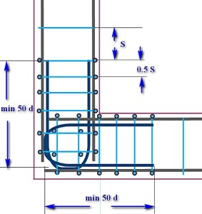
(In the diagrams, the border of the foundation tape is shown in burgundy colors, longitudinal bars of the longitudinal reinforcement are dark-gray, the wire clips of the frame are blue.) In addition, various specific elements of the gain node will be highlighted in various colors, which is specified in the text section. click the mouse).
| Scheme of reinforcing corners and contiguities | Brief description of the scheme |
|---|---|
| STRENGTHENING AT THE SITES OF DENTIST CHANGE OF THE DIRECTION OF THE FOUNDATION TAPE | |
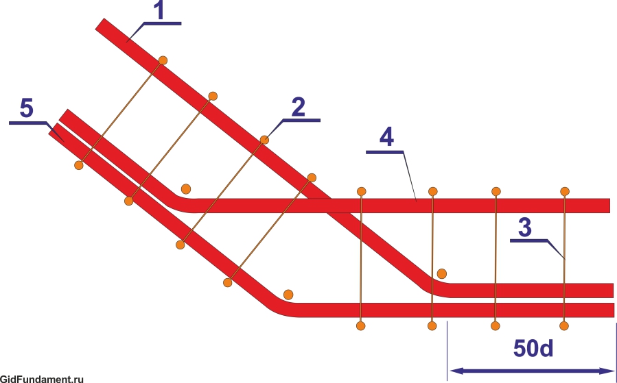
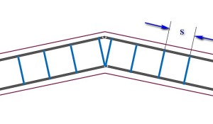 | If it is necessary to make an obtuse change in the direction of the foundation ribbon, provided that the angle exceeds 160 degrees, there can be no special amplification. Longitudinal armatures are bent at the right angle. The installation step of the clamps (S) is practically unchanged. The only feature - two clamps are put side by side in the bending point of the reinforcement, located on the inner contour of the belt. |
 | A similar, it would seem, situation, but the angle of the direction change though dull, but is less than 160 degrees. The amplification scheme is already different. The reinforcing bar, which runs along the outer circumference of the frame, simply bends according to the desired direction. Converging to the inner contour to the corner, the rods become longer, so that they intersect each other, reach the opposite side of the reinforcement belt, and end up with paws bent at the right angle (highlighted in red). The length of this curved leg part is not less than 50d (d is the diameter of the longitudinal reinforcement bar). The paws are tied to an external reinforcement rod, the clamping step being reduced by half in this section. At the top of the corner on the outer circumference, the vertical section of the reinforcement is additionally set (shown by the orange arrow). |
| STRENGTHENING IN DIRECT CORNERS AN ARMIRATING FRAMEWORK | |
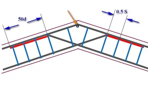
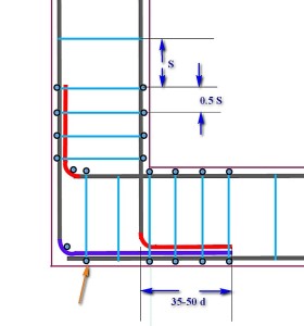 | A circuit with one large overlap and two "paws". The longitudinal armatures converging along the internal contour of the framework intersect each other, reach the opposite walls of the formwork, where they bend to form "legs" (shown in red) located in divergent directions. The minimum length of "paws" is from 35 to 50d. One armature on the outer contour is cut off in the corner, and the second, perpendicular to it, bends to form a large overlap (shown in purple), which should be so long as to at least completely cover the "foot". The entire structure is tied with clamps, the step of which should not exceed half the calculated one - 1 / 2S. The top of the bend angle is further strengthened by vertical reinforcement. |
 | A scheme similar to the previous one. Longitudinal armatures are also wound and bent by "paws," and instead of overlapping along the outer contour of the reinforcement, an L-shaped insert (shown in green) is installed. The length of each side of this insert is a minimum of 50d. Linking the unit - with the use of clamps, installed with a halved step. The rest is understandable according to the scheme. |
 | Scheme, convenient in the case when the skeletons on each side are knitted separately, and then stacked in the formwork. In this case, the intersection and linking of the frames to the overall construction is done using U-shaped inserts (shown in dark blue). The length of the "horns" of each of these pads is not less than 50d. Traditionally, in the reinforcement area, the step of setting the clamps is reduced by half from the design clamp. Note the additional reinforcement of the intersection of U-shaped inserts with vertical reinforcement. |
| STRENGTHENING OF SIDE LININGS OF THE FUNDAMENTAL TAPE | |
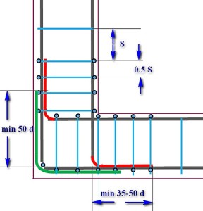
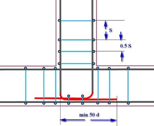 | Longitudinal reinforcement of the main foundation tape in the junction area is not interrupted. The longitudinal armatures of the adjacent tape intersect with the internal reinforcement contour, reach the outer side of the formwork and are bent by "paws" (red color), which are located in converging directions. The tying of clamps with the step reduced in half, and in addition to this, the section of intersection of the converging "legs" with the external longitudinal reinforcement of the main belt is further linked. The length of the paws is at least 50d. |
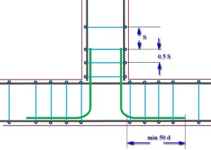 | Scheme, convenient for a separate assembly of adjacent reinforcement skeletons. The frame of the main tape is not interrupted, and the skeleton of the adjacent tape ends at the intersection line. Binding into a single construction is carried out with the help of L-inserts (green color), which connect the longitudinal reinforcement of the adjacent tape with the outer contours of the main one. The side length of such an insert is a minimum of 50d. All clamp connections are installed and tied together with a halved step. |
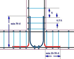 | Scheme of amplification of the junction area using a U-shaped insert. As in other cases, the skeleton of the main foundation tape is not interrupted. The longitudinal armatures of the adjacent frame are brought to the outer contour and bent by "paws" (red color), which are located in divergent directions. The length of the side of this foot is from 30 to 50d. The main reinforcement is made by a U-shaped insert (dark blue color) with a length of each of the "horns" of at least 50d. Linkage - with the traditionally halved installation step of the clamps. Additional co-ordination with the installation of vertical fittings - on the area of the lower part of the U-shaped insert to the outer contour of reinforcement of the main belt. |
It is necessary to understand one more nuance correctly. The schemes proposed in the table show the linking of the upper tier of the reinforcement belt. But exactly the same reinforcement should be provided in the lower belt, moreover, the maximum load usually falls on the lower part of the foundation tape.
Useful applications for calculating the number of required materials
Below the reader will be offered three calculators that will help in the calculation of the amount of material necessary to implement the chosen scheme of reinforcing the ribbon foundation.
Calculator for calculating the number of main fittings
For calculation the required quantity the main longitudinal reinforcement of the frame of the ribbon foundation is necessary to know several initial values:
- First of all, this is the total length of the foundation tape being created. Of course, not only the outer perimeter, but also all internal jumpers, if they are provided by the project, should enter here.
- The second parameter is the number of longitudinal reinforcement rods. How to determine this amount - was described above in this publication, with the application of the appropriate calculator.
- The third parameter is the number of amplification sites, also considered above. This includes all the angles and nodes of abutment of the foundation tapes. Naturally, in these areas the consumption of reinforcement increases.
The accounting program, in addition, will take into account the need for overlapping reinforcing bars on straight sections of the tape. The length of the overlap is assumed equal to 50d, that is, for the most frequently used diameters of the reinforcement it will be from 500 to 600 mm.
The calculator will give the result in a unit number of reinforcing bars of standard length (11.7 meters). Sometimes the complexity of transporting "lengthometers" forces customers to purchase rods cut in two (5.85 meters). On the one hand, transportation is simplified, but on the other hand, the amount of lapping of the reinforcement is inevitably increased during the installation of the frame, that is, the total required footage. In the calculation program, the second final value is also provided, expressed in the number of "split" rods. This will allow you to perform a reconciliation and make a subsequent choice in favor of the first or second option.