Series 1.423-3. Reinforced concrete columns of rectangular cross section for single-storey industrial buildings without bridge cranes up to 9.6 m high.
The modern construction of industrial buildings, shopping centers and many industrial premises requires seamless columns that can create frames without unnecessary operations. For this purpose, whole columns of different heights and bearing capacity have been developed, which serve as a support for rafters and sub-row structures of various severity. Columns K are buried in the foundations and become a reliable support of beams and trusses made of steel or factory reinforced concrete. Finished columns of reinforced concreteissue under strict requirements Issue 0 and GOST 25528-90. Like all reinforced concrete products, they are tested for strength, rigidity and crack resistance. Special control is designed for the location of embedded products, the slightest error in the location of steel parts will lead to great difficulties in the installation of trusses and beams.
Columns of single-storey buildings are a special type of product, which becomes the basis of panel or self-supporting walls, but does not tolerate loads from floors. The columns are made of heavy concrete M200, M300, M400 (B15-B40) with a modified composition. Heavy concrete is supplemented with air-entraining and plasticizing additives, which provide greater strength and crack resistance of products. Fire resistance of columns K - 3-4 hours, these products provide the highest safety of the object.
Typical series 1.423-3.
The current model series defines more than three hundred working drawings of columns for industrial buildings. The height of buildings up to 9.6 meters is achievable with the use of reinforced concrete columns included in issue 1. The 1.423.3 series itself contains six issues:
- Issue 0-1 Materials for design;
- Issue 0-2 Guidelines for the use of columns in areas with seismicity of 7.8, 9 points;
- Issue 1 - Working drawings of columns;
- Issue 1 - Bill of Materials (addition);
- Issue 2 - Reinforcement and embedded products, working drawings;
- Issue 3 - Working drawings of columns;
- Issue 4 - Working drawings for the reinforcement of columns 6.6 and 7.8 meters high.
Here columns of various lengths from 3 to 9, 8 meters are included, which are actively used to create spatial frameworks. Cross-sections of columns: 300х300, 300х400, 400х400, 400х500, 500х500, 500х600 mm. For the fastening of the column, the sub-columns corresponding to the sections are needed. The foundations for columns can be from 300x300 to 500x600 mm along the holes of the glasses. A separate issue determines the use of columns in seismic conditions, for this, certain measures are needed to strengthen the columns and foundations.
The construction of the column K
Reinforced concrete columns can have a constant square or rectangular cross-section or have headstones. According to the types of headstones of the series 1.423.-3 series and are divided into:
- Columns for supporting reinforced concrete beams and trusses;
- Columns for support of steel trusses "C";
- Columns for supporting reinforced concrete trusses with steel ties "A".
By design, the columns are also divided into columns of extreme and middle rows. Depending on the availability of embedded products for fastening columns and curtain walls columns can also be conditionally divided. According to the bearing capacity Issue 0 divides the columns of one-storey industrial buildings into 51 conditional types. The selection of column K takes place on the basis of keys, which contains a typical series 1.423-3. The reinforcement of columns is taken by spatial frames from longitudinal and transverse rods (A-I, A-III). Steel frames are installed according to the schemes in issue 2. Series 1.423-3. strictly defines the reinforcement of each type of columns, the diameters of the rods and the thickness of the protective concrete layer.
Columns in accordance with GOST 25528-90
The state standard defines columns of type K as products for building frames without bridge support and suspension cranes and buildings equipped with overhead cranes. Series 1.423-3 defines columns rectangular in height up to 9,8 meters which are actively used in any climatic conditions. In heated and unheated buildings, with wind pressure I-IV. The columns of reinforced concrete do not work in aggressive environments, but in the company "Complex-S" you can buy reinforced concrete columns prepared for work in conditions of aggression. Such products have a lower permeability of concrete and a high class of corrosion protection of frameworks and embedded products. Acquire reinforced concrete columns for GOST 25528-90 you can by prior order on the site "Complex-C". The sale of reinforced concrete products for industrial construction is carried out with delivery to your facility or warehouse anywhere in Russia and the CIS. Completing the construction sites with high-quality reinforced concrete is our task, the supplied columns and patella have the necessary technical passports and quality assurance.
TO Category:
Assembly of metal structures
Metal structures of single-storey industrial buildings
For industrial buildings, about 55% of the total volume of metal structures used for the construction of buildings and structures is used.
The metal frame of an industrial building (Figure 1) includes the following shipping elements.
The columns perceive the load from the cover, snow, bridge cranes, wind, walls and transfer this load through the foundations to the ground.
Crane beams perceive the concentrated pressure of the wheels of bridge cranes and their horizontal impact on the crane track. The horizontal stiffness of the upper girdle of the beam, which is necessary for the perception of the forces of transverse braking of bridge cranes, is provided by the upper belt and the horizontal braking truss.
Brake farms (decking) can be located on one side of the crane beam or between two beams. In Fig. 1 is a cross-sectional view of the brake flooring with a one-sided and two-sided arrangement of crane girders.
The rails for the movement of the skates of bridge cranes are fastened to the upper belt of crane girders. As crane rails use square steel from 50X50 to 140X140 mm, as well as railway or crane rails.
Rafter trusses perceive loads from their own weight, coating weight with insulation, lanterns, suspended hoisting equipment with cargo, overlapping, snow on the roof, and also against the impact of wind.
The lantern farms support the construction of glazing and roofing. Lanterns are arranged for ventilation and illumination of flights by side natural light.
Runs are supported by the ends on the upper belts of the trusses. Coverings are used for the runs.
Frames of industrial buildings also have shipping elements connecting columns with each other along the building. Podstropilnye farms, as a rule, are installed only in the middle rows of columns in multi-span buildings, if necessary, to increase the production area inside the workshop. The pitch of the trusses, and consequently the distances between the columns, take 6 or 12 m.
The upper vertical links, perceive wind load, acting on the end walls, and provide longitudinal rigidity of the upper part of the frame.

Fig. 1. Cross section of an industrial building: 1, 8 - columns, 2 - crane beam. 3, 6 - brake farms (decking), 4 - rafter, 5 - lantern farm, 7 - crane rails, 9 - run. 10 - channel
Columns of the truss, crane girders, girders, rails are load-bearing structures, as they perceive and carry not only the load from their own mass, but also from the mass of the coating, snow, impact of bridge cranes, wind. To the enclosing structures of buildings include: roofing, dropped ceilings, outdoor and internal walls, partitions, fences of openings (windows, lanterns, doors, gates).
Let us consider the structural features of the shipping elements of the frame of an industrial building.
The column (Figure 3) has the shape of a rod. The section of the column from the top to the support of the crane girder is the cranial part. The part of the column below the level of the support of the crane beam is the crane part. The column ends with a base. The base of the column has milled ends on the I-beam. The base is based on pre-assembled and verified in the process of installation supporting steel plates with planed upper plane. The plates are delivered by separate dispatch elements.
Columns in the middle part have crane consoles or platforms on which crane beams are supported. Columns are constant (Figure 3, a) or alternating (Figure 3, b) sections, solid and lattice. The solid-walled columns are made of sheet metal, I-beams and channels, which are joined together by welded seams.
Lattice columns have branches of I-beams, channel bars, corners connected by a grid. Lattice ensures the joint work of the column stem branches.
The trussed truss (Figure 4) is a planar grid structure. Farms have upper and lower belts, which are interconnected by a grid of corners. Vertical elements of the lattice are called struts, oblique - by braces. The grate angles with the corners of the belts are connected by sheet parts (fittings) to welding.
Rafter trusses transmit forces to the columns through mounting bolts and support tables with milled ends. In the horizontal shelves of the corners of the upper and lower belts, as well as in the racks of the truss, holes are made for fastening the ties. The upper belt has parts for installing and securing the lantern farm.
The most commonly used for industrial buildings are farms with a span of 18, 24, 30 and 36 m. The different types of trusses used in the frames of industrial buildings differ in the size of the spans, the slope of the upper belts, the geometry of the lattice, and the presence of lanterns. However, in principle, they are similar to each other.
Podstropilnye farms have parallel upper and lower belts. In the rack of the grill, located in the center of the farm, holes and tables for fastening trusses are made. Otherwise, the trunks do not differ from the trusses.
The lantern farms are supported by the upper belt of the trusses. They consist of an upper belt, pillars and braces made of corners. The corners of the upper belt are connected to the corners of the pillars and to the braces by sheet metal parts by welding or bolts.
Rafting and trimming trusses from corner steel and connections of the series 1.460-2, 1.460-3 and 1.460-4 are used in coatings with spans of 18, 24, 30 and 36 m reinforced concrete slabs and steel profiled flooring.
Connections are made from corners and pipes, at the ends of which there are sheet shapes for bolting them to the farms. Ties from pipes can have flattened ends in place of sheet shapes.
Crane girders consist of upper and lower belts, a vertical wall, stiffeners and end ribs. All parts are interconnected by weld seams (sometimes using riveted crane girders). The end fins have holes for fixing the crane beam to the column. The lower edges of the end edges are milled to transfer forces to the column. Crane beams in the form of trusses are also used.
![]()
Fig. 3. Columns: a - solid, constant section, b - latticed variable section; 1, 10 - I-beams, 2 - new undercuts, 3, 5 - crane girders, 4, 7 - crane and crane parts, 6 - support crane beam, 8 - base. 9 - support plate, 11 - grilles made of angular steel
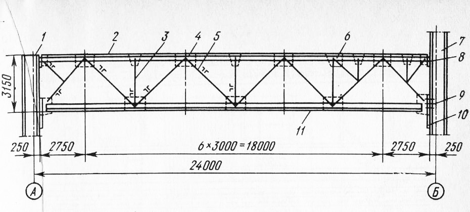
Fig. 4. Roof truss: 1, 7 - columns, 2, 11- upper and lower belts, 3 - stand, 4, 6 - slits, 5 - brace, 6, 9 - mounting bolts, 10 - support table
Standard beam spans 6 and 12 m series 1.426-1 are designed for industrial buildings with bridge cranes of up to 50 t lifting capacity.
Brake flooring is a sheet corrugated steel thickness of 6 .. .8 mm, reinforced with ribs or corners of stiffness.
Runs (span up to 6 m) are most often made of channels or I-beams, at the ends of which are made holes for attachment to the upper belts of the trusses. Runs of large spans are made through or from perforated beams.
Steel ladder flights (Figure 6, a) of the 1.459-2 series are produced with a slope of 45 and 60 °, a width (B) of 600, 800, 1000 mm and a height of (Я) 600, 1200, 1800, 2400, 3000, 3600, 4200 , 5400, 6000 mm. Kosovures 2 are made from bent profiles or channels, and steps 1 are made of sheet metal, drawn or corrugated steel and welded grating.
The transition platforms (figure 6, b) with the flooring have a width (B) of 50, 700 and 900 mm and a length (L) of 900 ... .6000 mm. Transition platforms are bent 5 from corrugated steel or welded from channels 4 and flooring from a welded grate or corrugated steel 3.
Enclosures of staircases and transitional platforms are made of equal-angled corners and strip steel.
In recent years, light structures of industrial buildings - fences, roofs, frames - have been increasingly used. The frame of buildings from such structures is delivered in a complete set.

Fig. 5. Crane beam: 1, 5 - upper and lower belts. 2 - vertical wall, 3 - stiffeners, 4 - end rib
Lightweight load-bearing and enclosing metal structures and components of metal products for single-storey industrial buildings. The following six types of lightweight load-bearing structures of one-story buildings are produced.
The frame constructions of box-type section "Orsk" have spans of 18 and 24 m with a frame pitch of 6 m. The frame consists of two steel racks, crossbars. Racks and crossbars of box section, consisting of channel bars No. 24 and No. 18, walls of sheet steel 3 ... 5 mm thick with longitudinal corrugations. Racks and crossbars of the frame have flanged mounting joints on high-strength bolts.
The sections of buildings with a spatial lattice covering of pipes of the type "Kislovodsk" have a size of 30X30 m. The structure of the section includes a structural plate, four columns with supporting plates and a set of passes with fasteners. The delivery set also includes a profiled roofing deck complete with fasteners. The plates of the plate are made of steel electrowelded and hot-rolled pipes with welded on the ends of the washers.
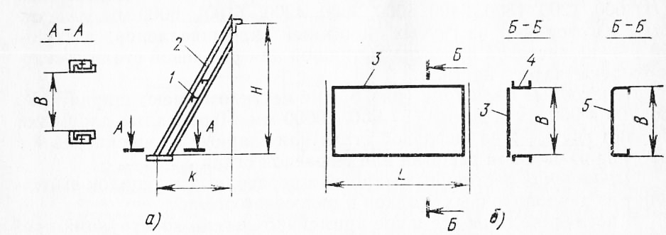
Fig. 6. Ladder march (o) and transitional platforms (b): 1 - step, 2-kosour. 3 - corrugated steel. 4 - channel channel. 5 - bent steel platform
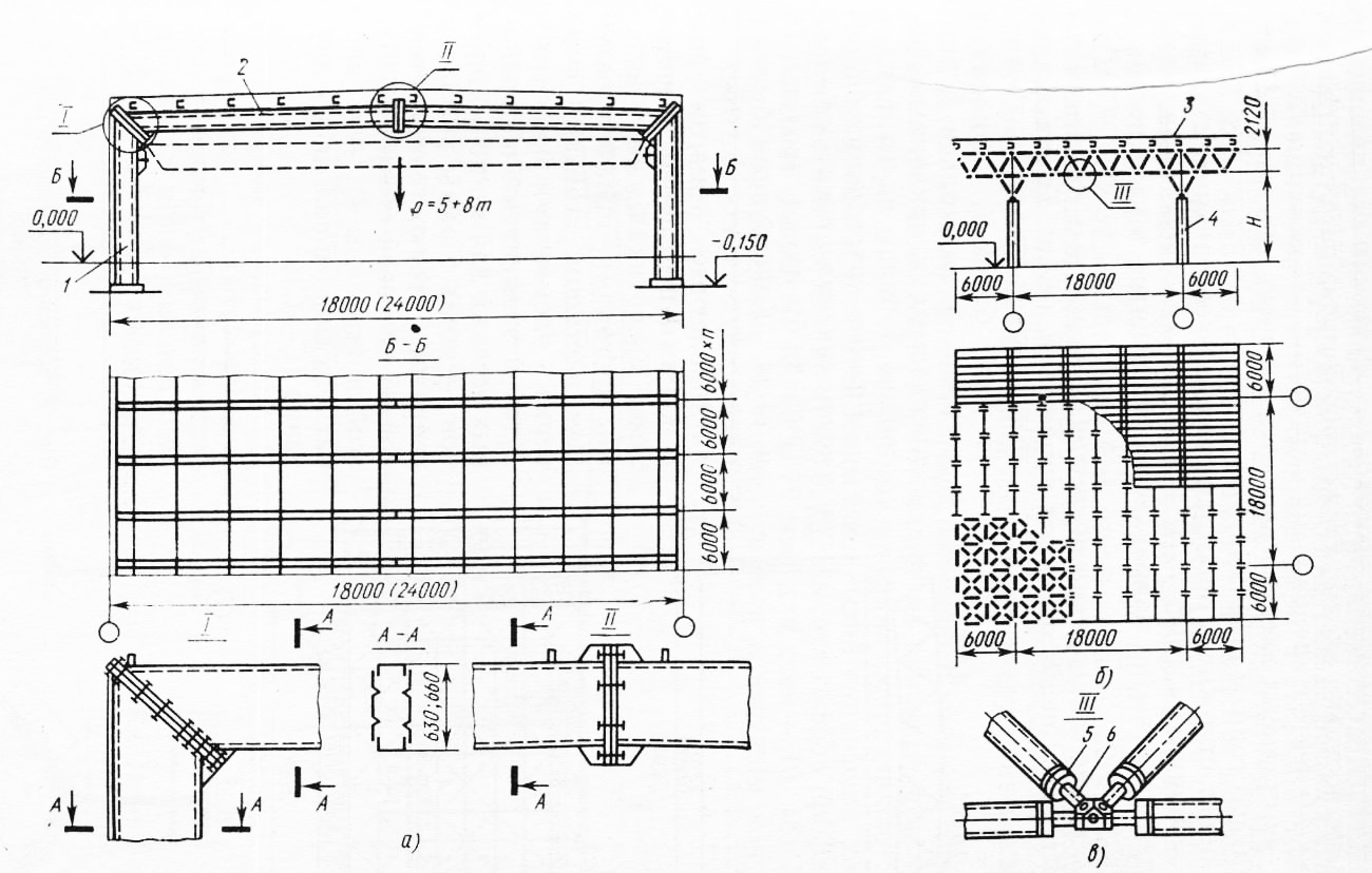
Fig. 7. Frameworks of industrial buildings: a-frame type, b - of structural structures, c - nodal element; 1 - rack, 2 - bolt, 3 - spatial grate plate, 4 - column, 5 - washer, 6 - coupling
Connect the rods to a spatial structure with steel polyhedra (Fig. 7, c) with threaded holes that are oriented in the direction of the belts and braces converging in the knot.
Structural structures of coatings from rolling profiles of the "CNIISK" type (p 8, a) have spans of 18 and 24 m. The horizontal elements of the plate are made of beams, inclined rods - from corners attached to the inclined beams of 3 beams on bolts.
Frame constructions of beam section type<гКанск» (рис. 8, б) имеют пролеты 18 и 24 м. Конструкции бывают одно-, двух-, трех-, четырех- и пятипролетные с шагом рам 6 м. Рамы поставляют в комплекте с вертикальными связями, прогонами, профилированным настилом, стойками фахверка, элементами подвесных путей и элементами подкрановых эстакад для мостовых кранов. Ригель 5 рамы выполнен сварным с тонкостенной стенкой из листовой стали (В-В), стойки (колонны 4) - из прокатного широкополочного двутавра (С-С).
The structures of the coatings from the cold-formed closed welded sections of rectangular section of the type "Molodejano" have spans of 18, 24 and 30 m, the pitch of the columns is 12 m, the pitch of the trusses is 4 m. The set includes headstones of columns, trusses and trusses, contour beams, vertical ties, spacers on the upper and lower belts of trusses and steel profiled flooring complete with fasteners. Belts and a lattice of trusses are made from the closed welded profiles of a rectangular cross-section with besfasonichnymi factory connections. Mounting joints of trusses - flanged on bolts.
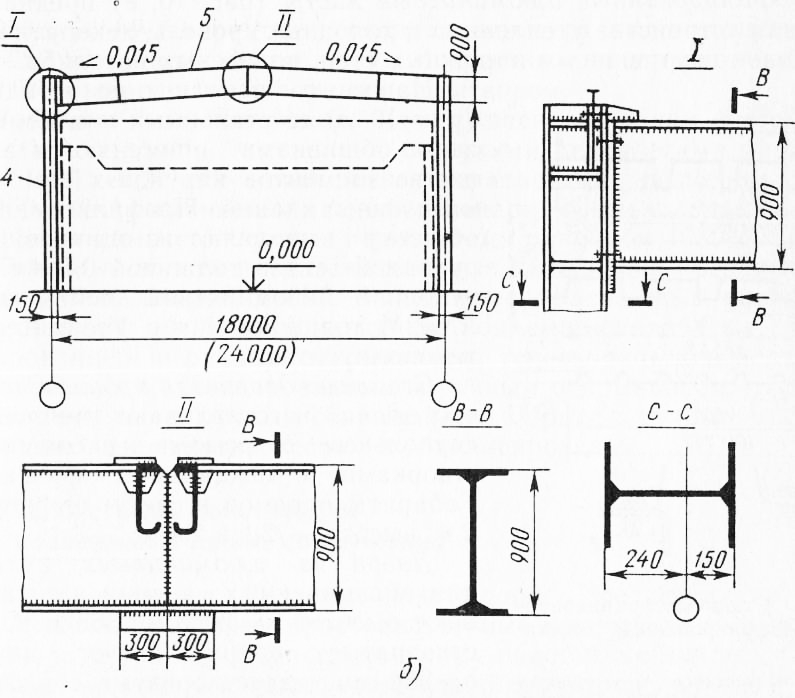
Fig. 8. Frameworks of industrial buildings: а - from structural structures of type "TSNIISK". 6 - frame type "Kansk"; 1 - beam, 2 - stsrzhnn of the corners, 3-fasonka, 4-column, 5 - bolt
The structures of the Ural round tube covers have spans of 18, 24 and 30 m, the step of the trusses is 6 m, the pitch of the columns is 12 m. Belts and a grid of trusses are made of round pipes with no-fitting connections. Mounting joints of trusses - flanged on bolts.
As the components produce the following types of metal products.
Steel zinced profiled floors with trapezoidal forms of corrugations are made of rolled steel with a thickness of 0.8; 0.9; 1 mm. Corrugated profiles are divided into two groups: profiles for insulated coatings and profiles for the stack of production buildings. The height of the corrugated profiles for insulated coverings is 40, 60 and 79 mm, for walls 10, 15, 18, 44 and 50 mm. Corrugated sheet profiles to supporting structures are attached by self-tapping screws. The profiles are joined together by combined rivets.
Window bindings for industrial buildings are made of steel or aluminum. Steel binders are made from bent welded tubes of rectangular cross-section 30X60 mm with glass fastening with aluminum profile or steel corner. Aluminum crossbars are made of elements of a box-shaped profile of a complex section formed by pressing.
The binders supply double separate blinds and with leaflets, single ones with leaf and blind ones, with lever and winch-opening mechanisms.
In Fig. 10, a is a window blind window blind with aluminum alloy flaps of height h = 1200, 1800, 2400 mm and width b = 2000, 3000 mm.
Panel aluminum partitions are designed for installation in single-storey and multi-storey buildings with increased requirements for sealing rooms, with a constant temperature-but-humidity regime. Separate partitions are produced (figure 10, b), door single-ended doors, double-leaf door ones with height / i = 3900, 4200, 4800 mm and width 6 = 1500 mm. Frameworks of partitions are supplied anodized in "natural color", i.e. under aluminum.
Profiled aluminum sheets are intended for the device of the warmed and cold roofs, decorative facing of internal and external walls, false ceilings.
Suspended sandwich panels with steel and aluminum sheathing are used as elements of the external walls of industrial buildings. The profiled sheathing is made of galvanized coiled steel 0.8 mm thick or a roll of aluminum tape AMG2M alloy 1 mm thick. Heater - polyurethane foam.
Steel doors for industrial buildings produce insulated double-faced with frames, swing doors and locking mechanism. Dimensions of openings in the light: width - 2 m, height - 2,1 and 2,4 m.
Doors made of aluminum alloys for public buildings are manufactured with a height of A = 2065 and 2365 m. Single-leaf doors have a width of 6 = 950 mm, bivalves with swinging equal flaps - 6 = 1450 II 1850 mm, bivalves with swinging unequal flaps - 6 = 1250 mm. Doors are delivered with colorless anodizing, fully glazed doors with a vestibule.
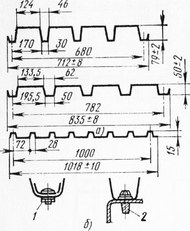
Fig. 9. Steel zinced profiled floors: a - types of decking, b - fastening methods; 1 - rivet, 2 - self-tapping bolt
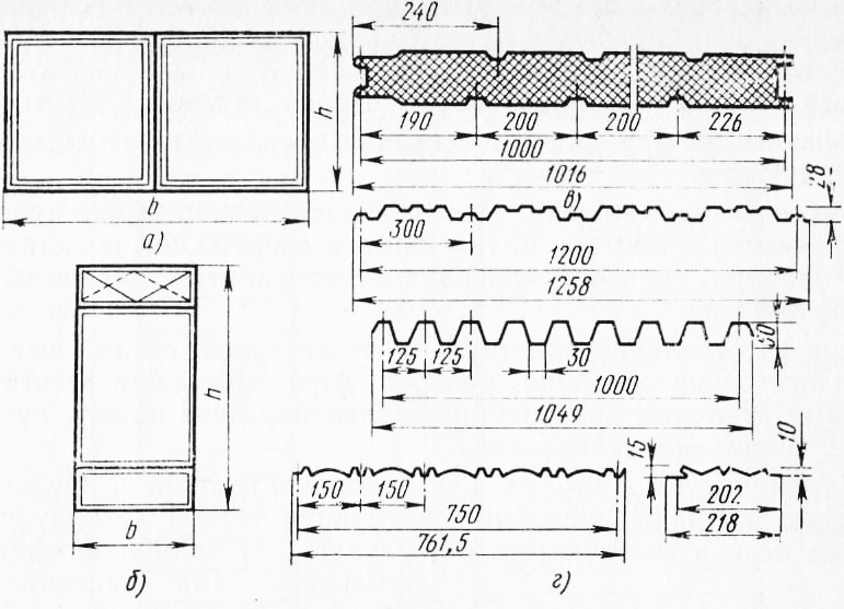
Fig. 10. Aluminum structures: a - window bindings, b - partition, in - a section of a three-layer panel, d - profiled sheets
Anti-aircraft steel lanterns for the illumination of the upper light of industrial buildings are supplied with blind bindings 980X1600 mm in size, with openable bindings measuring 735X X2950 mm. Aluminum zenithlights of industrial buildings are also produced with blind bindings of 1030X1640 mm.
Steel gates are designed to fill in the entrance openings of industrial buildings. Available: swinging, folding folded with manual opening, hoisting-folding with mechanized and manual opening, telescopic lifting-section with mechanized and manual opening, sliding with mechanical and manual opening. Gates with manual opening are equipped with counterbalances and balanced.
Federal Agency for Education
Kazan State University of Architecture and Civil Engineering
Chair of technology, organization and mechanization of construction
COURSE PROJECT
«DEVELOPMENT OF TECHNOLOGICAL CARD»
« Installation of reinforced concrete columns
one-storey industrial building »
Completed: Art. gr. 11-3s
Nesterova E.R.
Checked: Mavlyuberdinov A.R.
Kazan - 2009
1 area of use.
2. Organization and technology of the construction process, works.
4. Calculation of the cost of a pile, the time of work of machines and mechanisms, wages.
5. Schedule of work.
6. Material and technical resources.
8. Technical and economic indicators.
9. List of used literature.
1 area of use.
The technological map is designed for the installation of reinforced concrete columns of a single-storey industrial building in the summer season.
Columns with console.
Installation in a glass type of foundation with a conductor.
L = Length of the building - 72 meters
B = span of the building - 18 meters
Cross-section of columns - 0,4 m * 0,4 m;
The length of the column is 9.8 m;
The mark of the bottom of the beam is 8.4 m
Technical documentation on the organization of construction processes is made in the form of technological maps, which are typical and compiled; for the construction of a certain object. Typical technological maps usually make up for the execution of works during construction according to standard designs and in use require specification (binding) taking into account the construction.
Table 1. Statement of volumes of technological operations
2. Organization and technology of construction process, works.
Installation of columns using a conductor .
Installation of structures begins only after a thorough instrumental check of marks and position in terms of supports, supporting and embedded parts, the installation process has a decisive influence on the overall duration of construction and the organization of subsequent work. The installation of columns leads in the direction along the span of the building. With a span width of more than 18 m, the crane, moving along one of the rows of columns, establishes this series of columns, assembling one or two columns from one parking lot, returns and conducts the installation of the column from one parking lot, returns and monitors the columns of the other row. It is not advisable to install columns of the second row, because will cause a delay in the installation of the remaining structures due to insufficient strength of the joints. The conductor allows you to automate the process of aligning the columns and apply forced installation to the design position. The installation of columns is usually conducted by self-propelled boom and tower cranes. Columns of industrial buildings are mounted, pre-laying them at the installation site, or directly from vehicles, which they are fed into the zone of operation of the crane. From vehicles, the columns are mounted by a way of turning on weight.
Assembly of columns .
The columns delivered to the construction site are laid out so that during the installation the necessary movements and the volume of auxiliary work are minimal so that the columns are easily accessible for inspection, rigging and stitching. The columns are laid out not flat, but so that during the ascent the bending moment from the weight of the column and rigging operates in the plane of the column's greatest stiffness (this must be especially taken into account when installing two-branch columns).
Before the beginning of lifting the column, its length is measured with a steel tape measure, check the distance from the underside to the plane of the crane console or, in the absence of such, to the plane of support of the cover elements. If the distance to be measured is less than the projected one, you should "grout" the bottom of the foundation with cement mortar or install steel liners.
The installation of the column is started after the leveling layer of the cement slurry in the glass of the foundation has collected at least 70% of the design strength.
In addition, before the rise on the four facets of the column, axial risks are applied, as well as the axle crane axle axle.
The installation of the column is carried out by an independent flow. The crane moves along the span and installs 2 columns from one parking lot.
The column, installed in the glass of the foundation, is centered until the risks coincide with the risks on the upper plane of the foundation glass.
To verify the verticality of the columns, two theodolites are installed at right angles to the digital and letter axes of the building. In this case, the cross threads guide the risks on the glass and the bottom of the column, and then, smoothly lifting the theodolite pipe - at risk at the top end of the column.
Leveling of planes on the ends or consoles of columns on which the rafter structures and crane girders are installed are performed by marking marks or by a rail suspended from the leveling plane.
Adjusted columns are fixed in a glass of the foundation with the help of conductors or steel, wooden and reinforced concrete wedges. Reinforced wedges when reconciling the column and sealing the joint with a concrete mixture are not removed, but left in concrete. The wedges are installed two at each face of the column with a width of more than 400 mm.
Fig. 7. Means for reconciling and temporary fastening of columns in the foundations of the foundations: a - calculation scheme; b - conductor diagram; в - a wedge loose leaf; г - the mechanism a jack
As a rule, the lower columns are installed on the glass-type foundations, verified and fixed in them, as well as columns of single-storey buildings. And the columns of the following floors are already installed on the upper ends of the columns below, or on the crossbars.
Practice installation, reconciliation and temporary fastening of columns in the following three ways:
Installation of risks with alignment of verticality plumb and welding of parts of butt joints. To ensure the verticality of the columns when reconciling, when necessary, pullers are used. This method is used for the installation of columns with platform-type joints. It can be used for the installation of columns with milled steel plates along the ends, but then the temporary fastening is done with bolts, for which the corners are pre-welded to the embedded parts;
Installation of columns on the heads of columns, on which pre-fastened with screws, single conductors (the heads of the lower columns are usually above the level of overlapping by 0.5-0.8 m). The column installed in the conductor is fixed with adjusting screws and aligned along the center and vertical axes. Various designs of single conductors are used;
Installation of columns on the heads of the lower columns with temporary fastening and reconciliation by means of group conductors for four columns. The group conductor is installed and fastened with clamps to the ends of the columns set below. Each of the four columns is installed, fixed and reconciled in the same way as installations with single conductors. The deck with fences at the top of the conductor allows you to mount the structure of the floors. After finishing the installation work and fixing the elements in one cell of the building, the conductor is moved to the next cell. On the next floor conductors raise the crane.
The most common group conductor is the frame-hinged indicator (NDT). The SIR is a device consisting of three-dimensional lattice scaffolds on which there is a hinged (floating) frame with corner stops for the fastening of four columns at the top, retractable and rotary cradles for installers and welders. At the corners of the frame for temporary fastening of columns in the design position, angular faceted fasteners (stops) are installed - two swivel locks and two flaps, which can occupy the transport or working position and do not interfere with the installation of crossbars and plates.
With the help of this conductor, the columns are mounted without additional alignment. They are raised one by one, brought to the appropriate locks of the conductor by the crane and smoothly lowered to the heads of the lower columns. The lateral edges of the bottom of the mounted column are attached with a tensioning device of the lower lock fixed to the head of the column, tightly pulling to the edges of the lock. In this way, they are precisely aligned with the corresponding faces of the column head. The top of the column is fixed with the upper grip - the indicator frame lock, bringing the column to a strictly vertical position.
Zamonolichivanie joints and reinforced concrete structures:
Zamonolichivanie joints and joints with mortar or concrete mixture are made after reconciliation of the correct installation of structural elements, acceptance of welded joints and the implementation of anti-corrosion protection of steel fittings and release reinforcing bars. The concrete or mortar mixture is fed into the joint under pressure either mechanically or manually. The process of filling joints and seams with mortar and concrete mix consists of feeding and laying in mortar or concrete mixes with subsequent consolidation.
Organization of labor of workers:
The organization of workers' labor in construction includes the appropriate arrangement of people in the production process, the division into labor cooperation, methods of rationing and stimulating labor, the organization of jobs, their servicing and the necessary working conditions. The scientific organization of labor requires the constant improvement of labor processes on the basis of the latest achievements of science and practice aimed at the steady growth of labor productivity, the improvement of conditions and the enhancement of the culture of labor, the transformation of labor into a vital need.
The scientific organization of labor is created on the basis of a complex of technical, organizational and economic measures that ensure the most rational division and cooperation of labor, the improvement of labor processes and the organization of workplaces.
Methods of organizing labor can be different, depending on the structures used, methods of work, machines, installations and other means of production.
To perform various operations in the construction process, the workers are grouped into links depending on the nature of the operations that the link or brigade must perform. The links consist mostly of two or three workers of the same profession, but of different qualifications.
Several links, performing the same construction process, are united in a brigade headed by a brigadier.
Brigades are specialized and complex. The specialized brigade consists of workers of one specialty, numbering up to 25 people. Complex brigades unite workers of different professions to perform a certain complex of works, part or whole of the structure. The integrated brigade includes about 50 workers.
A final product team is organized to erect certain structural elements (foundations, walls, floors, etc.) or a building (structure) as a whole.
Every year the number of brigades of workers performing work by the brigade contract method on the basis of economic calculation increases. Brigade contract is transferred as a team of general contractor and subcontractor. The transfer of teams to the economic calculation should be preceded by the development of work schedules, the supply of basic materials, structures, products, the calculation of labor costs and wages, and the cost of the work assigned to the brigade.
One of the important indicators of the activity of construction workers is labor productivity, that is, the amount of time spent per unit of output, defined in man-hours or man-days. The less labor costs per person per hour per unit of output, for example, per 1 m3 of brickwork, per m2 of plastered surface, etc., the higher the productivity of labor.
Construction processes at the construction site or part of the facility are performed in a certain order (combining in time), ensuring the rhythm of production and the most rational use of labor and technical means. The object is divided into captures, i.e., areas where there is sufficient work to perform the construction process by the brigade for a certain time (usually at least one shift). The number of seizures should be sufficient so that brigades of different professions can perform construction processes at once, moving after finishing work from one capture to another. For some processes, the seizure is divided by height into longlines, for example, with brick masonry, which can not be immediately performed on the height of the floor and which requires a scaffold device. Part of the clamp, allocated for one worker's work, is called a plot.
The space in which the workers involved in production are located, and also the machines, materials and parts necessary for the construction process are located and moved, are called the workplace. The site allocated for the work of the brigade or the unit for a certain period of time is called the work front. The size of the work front depends on the size of the team engaged in the construction process. The work front is measured in units of length, area or volume. For the correct organization of complex building processes, technical documentation is developed at the facility, in which the nature of the process and its composition, methods of production and means of mechanization of work, a schedule of production, the required number of workers by profession and their qualifications, materials, parts, tools and the organization of the workplace.
Sometimes an object of construction is conventionally dismembered vertically into technological layers. The need for such dismemberment arises when, on the basis of the structural features of the object, the front of the work is opened in the course of their implementation. For example, when concrete columns are concreted by lowering the concrete mix from above, while the height of the line according to SNiP should not exceed 5 m to avoid the stratification of the concrete mixture during its fall.
Table 2. Qualification of the brigade or unit
| Unit number | Running processes | Qualifying composition of workers | Number of workers |
| 1 | Installation of columns in a glass of the foundation | Assembler of constructions of 5 category | 1 |
| 1 | |||
| Assembler of constructions of 3 categories | 2 | ||
| Assembly erector of 2 categories | 1 | ||
| Crane operator of 6 category | 1 | ||
| 2 | Sealing joints | Assembler of constructions of 4 categories | 1 |
Assembling of constructions 3 |
1 |
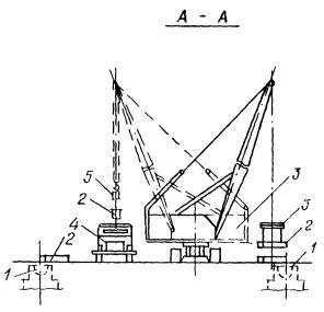
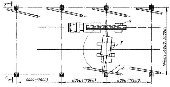
Fig. 1.1. Scheme of unloading and pre-laying of columns in buildings by span 12, 18, 24 m.
1 - a glass of the foundation; 2 - column; 3 - vehicle; 4 - the crane; 5 - traverse.
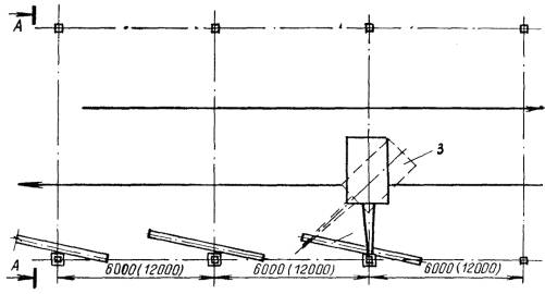

Fig. 1.2. Scheme of installation of columns in buildings span 12, 18, 24 m:
1 - a glass of the foundation; 2 - column; 3 - vehicle; 4 - the crane; 5 - traverse.
Reconciliation and temporary fastening of columns are carried out by inventory wedges or conductors. And for the columns of 8 t, the conductor is installed on the foundation and fixed on the column after it is installed in the foundation glass. For heavier columns, conductors are installed, verified and fixed on the foundation before the installation of the column begins.
After the installation of a number of columns, their design position is finally verified and the embedment of column joints with foundations is made. Columns for embedding are given in lots.
Scheme of montage of single-storey industrial buildings :
Columns are delivered to the construction site by road, while light columns (up to 8 tons in weight) are mounted with a pre-layout at the installation site in the range of the crane, and heavy ones are delivered to the installation crane on an hourly schedule and mounted directly from vehicles.
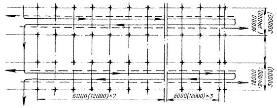
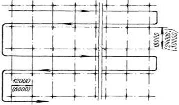
Fig. 1.3.Chemes of motion of the crane when installing columns in spans 12, 18, 24 m.
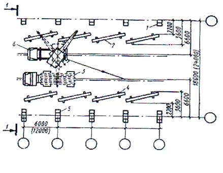
Fig. 1.4. Scheme of unloading and laying crane beams span 6 and 12 m:
1 - column of the extreme row; 2 - crane beam; 3 - the tank truck; 4 - wooden lining; 5 - column of the middle row; 6 - car crane; 7 - pull on the hemp rope; 8 - Lanyard.
Depending on the size of the span (12, 18, 24 m and more) and the pitch of the columns (6; 12 m), various schemes of column mounting and movement of mounting cranes are used (Figures 1.2, 1.3, 1.4).
Crane beams are expediently mounted by a separate flow directly from vehicles. The installation of beams in the design position is carried out on axial risks on the beams and consoles of the columns. The beams are temporarily fixed on the supports using anchor bolts. The final alignment of the crane girders is carried out within the erection or temperature section, using geodetic tools, after which all the fasteners of the beams and the embedded parts of the columns are inspected.
Methods of laying the columns before the installation: a - light; b - heavy;

For the installation of light columns of single-storey buildings with arrow valves, a forked headband can be used, which is in the form of a console attachment to the boom head that has blocks for rope stock. The cushion is equipped with a device for semi-automatic passtepping. It allows the use of cranes with a smaller boom length and, therefore, more fully use their load capacity. In addition, the minimum length of the suspension reduces the swaying of the column and allows their carrying capacity. In addition, the minimum length of the suspension reduces the swaying of the column and improves the mounting accuracy.
If necessary, the bottom of the glass is leveled with a layer of cement mortar. The columns are installed in the basement cups after the strength of this solution reaches at least 70% of the design. Reconciliation and temporary fastening of columns, depending on their size, mass and location of installation, are carried out with the help of individual conductors of inventory steel, wooden, reinforced concrete wedges (two at each face of the column).
The column installed in the foundation glass is centered until the risks coincide with the risks on the upper plane of the foundation.
To check the verticality of the column, two theodolites are positioned at right angles to the digital and letter axes of the buildings. In this case, the visual axis of the theodolite is combined with the risks deposited on the glass in the lower part of the column, and then, smoothly lifting the theodolite tube, with the risk at the top end of the column. The distance outside the theodolite from the column to be reconciled is assumed to be such that, at the maximum rise of the pipe, its angle of inclination does not exceed 30-35 '.
The planes on the ends or consoles of the columns are leveled by marked marks or by a rail suspended from the leveling plane.
Adjusted columns are fixed in a glass of the foundation with the help of conductors.
Design of warehouse structures
Storage of prefabricated structures is carried out in stacks or cassettes in which vertically positioned structures are placed - wall panels, trusses, etc.
Passages between the stacks are arranged with a width of 0.4 to 1 m and are located through 2 stacks in the longitudinal.
Tracks 3 ... 4 m wide for the movement of vehicles and loading and unloading mechanisms are arranged not less than 100 m.
The width of the warehouses is taken from the calculation that all items are lifted from the warehouse without additional percussion and displacement, i.e. they must enter the service area of the service cranes.
In the warehouse, prefabricated elements are positioned in the same position as on vehicles during transport. Horizontally stored structures are laid on wooden pads, the distance between which is coordinated with the working conditions of this structure.
The layout of the items in the warehouse can be separate, in which all the elements of the same type are stored together and grouped, when layout and installation of different types of elements from one parking lot of the crane is ensured.
Construction site roads
Roads of construction include access roads that connect the construction site with a common network of highways, and in-built roads, which transport goods inside the site. Access roads, as a rule, are permanent, but in-built before the construction of the main facilities.
Roads on construction sites can be dead-end and circular. At the end of the dead-end, there must be turning platforms, and in the middle part, if necessary, - crossings. Proceeding from the normative dimensions of the car (a rectangle with a width of 2.5 and a height of 3.8 m), the width of the carriageway of the road with a single-lane road is 6 m. If the road is designed with a single-lane, then in the intended unloading areas, broadening should be provided, not less than 6 m.
When heavy vehicles are used, the carrying capacity of 25 ... 30 tons or more will increase the width of the carriageway to 8 m. If the road construction site is delivered with large and long loads, the width of the road can be further increased.
The radius of the rounding of roads is dictated by the possibilities of maneuvering individual machines and road trains, i.e. their turnability when moving forward without using a reverse. Usually the minimum radius of curvature is taken to be 15 m, at this point the width of the roadway is increased - at a width of 3.5 m on the rounding it will be 5 m.
Structurally, motor roads consist of an earthen cloth and pavement. To divert surface water on the straight sections of the road, the road is given a two-slope gradient, and on the curved ones - a single-slope road.
Road clothing consists of several layers - the underlying sand layer, the supporting base (crushed stone, concrete, reinforced concrete) and coatings. To reduce the costs for the construction period on the construction site, it is advisable to build future permanent roads without top cover. Only the lower layers of the road are arranged, it is even more effective to lay a temporary covering of reinforced concrete road plates along the sand base. The main covering in this case should be performed before putting the object into operation.
As reinforced concrete road slabs plates are used that are rectangular in plan and wedge shaped. Rectangular road plates (length 2.5 ... .3 m, width 1.0 ... 1.5 m, thickness 0.14 ... 0.22 m and weight 0.63 ... 1.8 t) are easy to manufacture and in work with them on the construction site, can take on high loads, are suitable for operation immediately after their laying at any time of the year and in any weather. Roads are more often arranged by track - one - and two-track with traveling. Wedge-shaped slabs allow you to arrange roadway coverings immediately on the entire width of the road, the radius of curvature at corners can be any. On the straight sections of the plate alternate, placing them then a broad, then a narrow side. For such slabs, there is no need in the device of separate sections of the road (especially at corners) in monolithic design.
Costs for the device, repair and maintenance of such roads in conditions typical for building traffic intensity usually pay for 1.5 ... 2 years. Prefabricated - demountable plates are the property of the building organization and assume their repeated use.
Loading and unloading of construction cargo
Transportation of construction cargo to the facility is associated with the need for their loading at the place of departure and unloading at the place of arrival. These operations are almost completely mechanized, general construction and special machines are used for their implementation or are part of the constructive solution of vehicles.
The first group includes special assembly cranes, cyclic and continuous loaders, mobile belt conveyors, mechanical shovels, pneumatic unloaders, etc. The second group includes vehicles - dump trucks, vehicles with self-unloading platforms and autonomous unloading means, etc.
In construction, the use of transportation of small pieces and products with the use of packages and containers finds application. Package - a consignment of cargo loaded on a special pallet. Packages should be formed in such a way that their form is preserved at all stages of the movement.
A container is an inventory multi-turn device or container. Universal container is designed for transportation of various categories of goods; it is closed, equipped with devices for loading and unloading. Special containers are designed to transport a certain type of cargo - roll materials, finishing tiles, linoleum, wiring fittings to the section of the building, etc.
Warehousing of material elements
The material elements delivered to the construction site are stored on the on-site warehouses intended for their temporary storage - creation of a production stock.
There are two main types of production stocks - current and insurance. The current stock is the material resource between two adjacent deliveries. Ideally, the current stock should be sufficient to ensure continuous production. However, given possible disruptions in the supply of materials and structures, create an insurance stock, which should smooth out, compensate for the unevenness of replenishment of the current stock. The minimum stock of prefabricated structures in a warehouse is usually taken for 5 days of work.
The level of the production stock depends on the organization of work - mounting "from the wheels" or from the warehouse, the remoteness of the object from the central support bases, the mode of transport and other factors. The presence of a warehouse with excessive stock of structures or materials, on the one hand, ensures the uninterrupted production of work, and on the other hand, leads to a "freezing" of investments in this construction, i.e. to its rise in price. Therefore, the general contractor must find the optimal volumes of on-site warehouses. On-object warehouses arrange closed, semi-closed and open.
Closed warehouses serve to store expensive materials that are deteriorating outdoors - cement, lime, gypsum, plywood, nails, etc. They can be overground and underground, single-story and multi-storey, heated and unheated.
Sheds - semi-closed warehouses are erected for materials that do not change their properties from changes in temperature and humidity, but require protection from direct exposure to the sun and atmospheric precipitation - wood products, asbestos cement, roofing material, other fencing and finishing materials.
Open warehouses are designed to store materials that do not require protection from atmospheric influences - brick, concrete and reinforced concrete elements, ceramic pipes, etc. Warehouses are usually located in the operating area of the installation crane serving the facility. This allows it to be used for unloading incoming goods, mainly in their spare time or in a shift-free shift. During the installation process, it is advisable to use lighter self-propelled cranes for unloading operations.
Part of the open warehouse, including the site of aggregate assembly of structures, can be serviced by special cranes - self-propelled on caterpillar and pneumatic travel, gantry, tower cranes - forklifts. These mechanisms are used to load enlarged structures to vehicles for their subsequent delivery to the places of installation or installation. Usually in the warehouse, heavy loads are laid closer to the cranes, and the lungs are farther away, since they can be lifted at a higher crane reach.
The storage areas should be level, with a slight slope of between 2 ... 5% for storm water and meltwater runoff. On poorly draining soils, in addition to planning, it is recommended to make a small pile of rubble or sand - 5 ... 10 cm. If necessary, surface compaction is carried out. Plots of storage area, where materials (mortar, sand, etc.) are unloaded directly from vehicles, should be carried out in the same constructive solution as adjacent access roads.
For different designs and prefabricated items, they divert their storage areas. They are separated from one another by passages with a width of at least 1 m. For different materials, there are different storage rules.
The brick is stored in grades, grades, the color of the front surface. The brick, delivered in bulk, is stacked with a bandage and a height of 1.6 m, with a brick with blind cavities down. Brick in packages or on pallets can be stacked in a warehouse in one or two tiers.
Prefabricated reinforced concrete is located on inventory pads and gaskets, the places of installation of which must correspond to the risks on prefabricated elements. When storing elements in the stack, the spacers between them are stacked one above the other strictly vertically. The section of the gaskets and linings is usually square, with a side of 6 ... .8 cm. The dimensions are chosen so that the overlying elements do not rest on the mounting loops or protruding parts of the underlying elements.
Before assembling the columns, you should:
· Concrete or install foundations for columns and verify compliance with their design position using geodetic tools;
· Fill up the sinuses of the foundations;
· Apply the risks of locating axes on the top of the foundations and lateral faces of the columns;
· Close the foundation glasses with shields to prevent contamination;
· Arrange roads for the crane and cars;
· Prepare sites for storing columns at the installation site;
· Deliver the necessary mounting means, tools and tools to the installation area.
Reinforced concrete columns on the object are laid out on wooden pads in the area of the installation crane. The thickness of the pads must be at least 25 mm.
If there are no mounting loops, the columns are stitched with a hinge at the locations indicated at the factory. The cable must not have nodes and twists. To protect the rope from kinks and rubbing under the ribs of the columns, steel pads should be put.
Each column must be inspected to ensure that it does not have deformations, damages, cracks, shells, chips, naked reinforcement, concrete inflows; check the geometric dimensions of the column, the presence of a mounting hole, the correct installation of steel fittings.
For reconciliation and temporary fastening of columns a set of mounting hardware is used, placed in a container. The kit includes inventory wedges and other devices (RF-595 CNIIOMTP).
Performers:
· Worker, performing assembly works, senior in the link;
· Worker performing assembly work;
· Worker performing rigging.
Work technology
Preparation of the column for installation (Figure 13), the executor working, performing rigging works
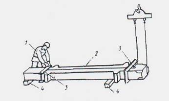
Preparing the column for installation .
Rigger
1. Check the marking of the column.
2. Cleans the ends of the column with a metal brush from the influx of concrete and dirt.
3. Using a metal meter, divides one plane in width into two equal parts in two places (at the top level of the basement and at the top of the column) and punctures axial risks with a pencil.
4. By analogous methods, it puts risks on the second plane perpendicular to the first.
5. Gives the signal to the crane operator to feed the universal gripper 3 to the column 2.
6. Attaches from the top end of the column grip and using the inventory handle twists the nuts of the clamping device.
7. Leaves a distance of 7 ... 8 m from the column.
8. Gives the signal to the crane operator to lift the column to a height of 200-300 mm.
9. Inspect the fixtures.
10. Gives the signal to the crane operator to deliver the structure to the installation area
Preparing the installation site
Assemblers of the 1 st, 2 nd
1. The 2 nd installer is laying out tools, fixtures, tools.
2. Then checks the cleanliness of the glass foundation.
3. After checking the risks on the top plane of the foundation glass.
4. The 1 st and 2 nd installers lay out the tools and adaptations according to the scheme of organization of the workplace.
5. The first installer installs and reconciles the two theodolites.
Receiving, installing and securing the column
Reconciling the column with a single conductor
Assemblers of the 1 st, 2 nd
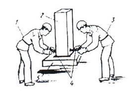
Fig. 16. Scheme of alignment of the column jacks:
1 - worker, performing assembly works, senior in the link, 2 - column, 3 - worker, performing assembly work, 4 - jack, 5 - foundation
Installers install two jacks 4 from opposite sides of the column and rest their screws in the plane of the structure
2. The first installer checks the coincidence of axial risks on the column and the glass of the foundation 5 and gives a signal for the displacement of the bottom of the column in the desired direction.
3. The 2 nd installer twists the jack screw, which moves the column, and at the second jack the screw loosens.
4. After receiving a combination of risks, installers rearrange the jacks on the other axis of the column and, with similar movements, align the element with respect to the second axis.
5. Assemblers take one conductor of a conductor and install it on the foundation glass on both sides of the column.
6. Installers tighten the tightening bolts, connecting small chambers.
7. The 1st installer gives the signal to the crane operator to loosen the lines.
The installers produce a column shredding (see below).
9. The first installer sets the axis of the first theodolite pipe at risk in the lower part of the column and fixes the horizontal circle.
10. Then he moves the theodolite pipe to risk at the top of the column.
11. If there are deviations, the 1st installer gives the signal to the 2nd installer to mix the top of the column.
12. The 2-nd installer rotates the screw of the corresponding support of the conductor moves the top of the column in the desired direction.
13. Similarly, reconciliation is carried out in the other direction.
String Lining
Assemblers of the 1 st, 2 nd

Fig. 17. Scheme of column unbuttoning:
Column, 2 - clamps of the clamping device, 3 - worker, performing assembly work
1. The 1st installer gives the signal to the crane operator to loosen the lines.
2. The 2-nd installer using the inventory handle loosens the nuts of the two threaded couplers of the clamping device 2.
3. The first installer removes the ties from the slats and gives the signal to the crane operator to raise the grip.
3. Requirements for quality and acceptance of work.
Prior to the commencement of work on the installation of columns, the following organizational and preparatory measures should be performed:
The structures must pass the incoming quality control and meet the requirements of the design and regulatory documentation;
The foundations for the columns were erected;
Preparation and layout of the installation site with backfilling of the sinuses of the foundations was made;
The installation axes (risks) are placed on the cups of foundations ";
"The act of intermediate acceptance of foundations" is issued.
The installation of columns should be carried out only after the acceptance of foundations and other support elements, including a geodetic check of the compliance of the planned and altitude position with the project.
Operational control of the quality of the installation of columns .
Operational quality control
| The name of the operations subject to control | Subject of control | Technical requirements for the quality of operations | Methods and means of control | Time control | The involved supervised services |
| Preparation of structures for installation | Appearance of constructions | Absence of structural defects, their integrity, compliance with design requirements of the project | Visually | Before work starts | |
| Correspondence of the design marks to the project | The marking of structures must correspond to the design | ||||
| Correct application of installation risks | On the structures to be mounted, the installation axes, the fixing centers of the sides | ||||
| Preparing the location of the columns | Cleanliness of the surface of the base for the installation of structures | The surface of the base for the installation of columns should be cleaned of dirt and water, metal parts must be degreased, cleaned from corrosion, solution | |||
| The presence of an executive scheme for the installation of foundations | The installation of columns should be carried out only if there is an executive scheme for the foundation device, indicating the mounting marks of the prepared gravy | ||||
| Installation of columns | Compliance with the technological sequence of the installation of columns | The technological sequence of production should comply with the requirements specified in the technological map | According to the technological map | ||
Columns should be installed by combining the risks that designate the geometric axes in the lower section of the structure to be mounted with the figures: Breakdown axes when installing columns in the cups of foundations; Geometric axes of the below-installation structures; In all other cases. |
surveyor | ||||
| Installation of columns | Correspondence of installation of columns to adjusting risks | In the presence of embedded fixing devices, the installation of columns must be performed on these devices. The displacement of the axes of the columns in the lower section relative to the centering axes (scales) should not be more than 5 mm | Instrumental: theodolite, metal meter | During the production process | Surveyor |
| Vertical installation | The deviation of the column axes in the upper section relative to the centering axes should be at the height of the columns, m: Up to 8 ...... .20mm; From 8 to 16 ... .25mm; From 16 to 25 ... .32 mm; From 25 to 40 ... .40mm; |
||||
| Correspondence of the marks of the top of the columns by the project | Deviation of marks of the top of columns or their support areas of single-storey buildings from design should not exceed 10 mm. A variation of the marks of the tops of columns or their support areas for each tier or floor within the area to be verified, mm: for a contact installation (where n is the sequence number of the line) 12 + 2 n | Instrumental: measuring tape, metal meter |
| Clamping of assembly units | Quality of column embedding in glasses of foundations | The fastening of the columns to the design position should be done by embedding the joint of the columns with the basement glass with a concrete mixture on small gravel or rubble with a mark corresponding to the concrete or the project | laboratory | After installation of structures | laboratory |
| Quality of embedding of joints of mounted columns | When embedding the joints of the assembled columns with previously installed columns, the joints of the columns must be sealed by injecting the finished concrete mix of the design mark onto the formwork joint | According to the technological map | After mounting the structure | Laboratory |
|
| The actual position of the mounted columns | After the complete elimination of impermissible deviations and the final fixing of the structures, a geodetic survey of the actual position of the structures must be performed with the drawing up of an executive scheme of the floor of the building or structure | Upon completion of work | Engineer surveyor |
6. Material and technical resources
Table 6. The need for basic materials, semi-finished products and structures
Table 7. The need for machinery, equipment, tools and devices
| Name | Make | Number of | Specifications |
| 1 | 2 | 3 | 4 |
| Crane | ICG-25BR | 1 | |
| Conductor | |||
| TARA | |||
| Bunker for concrete, V = 1 m3 | GOST 21807 - 76 | 3 | |
| Boil of solution, V = 0,3 m3 | 4 | ||
| Water tank, V = 1 m3 | 1 | ||
| Warehouse - container for tools | 1 | ||
| SAFETY FACILITIES | |||
| Fencing of the construction site | |||
| Signal fence | |||
| Rack fence rail | |||
| Safety harness for installers | 1 | ||
| Mast searchlight mobile | 1 | ||
| Lamp for workplace lighting | 2 | ||
| Construction helmet | GOST 12.4.087.84 | 5 - 7 | |
| Fuse Belt | 5 – 7 | ||
| Technical rubber gloves | 2 | ||
| Flag alarm | 2 | ||
| Protective spectacles | 2 | ||
| MEASURING TOOL | |||
| Theodolite T-15 or T-30 in a complex with a stand SR-40 | |||
| Leveling NT for reconciliation of the horizon complete with a stand ШТ - 120 | |||
| Rake leveling | 2 | ||
Roulette metal P3 - 20, |
|||
| Metal folding metal meter MCM-74 | |||
| The level of construction HSS-500 | GOST 9416-83 | ||
Plumb-line steel building OT-400 |
GOST 7948-80 |
||
| Steel angle bracket | GOST 3749-77 | 2 | |
| Roulette | GOST 7502-98 | 2 | |
| Strip marking in the case | 1 | ||
| Rake with level | 4 | ||
| Set of crayons for marking axes | 1 | ||
| Scribe OTD-967/2 | 2 | ||
| Spanners for assembly of bolts 18-27 mm | 2 | ||
| End Assembly Keys for Bolts 18-27 mm | 1 | ||
| Keys one-sided (colic) for bolts 18-27 mm | 1 | ||
| Single-sided spanners for bolts 27mm | |||
| Construction scrap LL-28A | 4 | ||
| Scrap mounting LM-24 (LM-32) | 4 | ||
| Construction spade | 4 | ||
| Spade mortar LR | 4 | ||
| Trowel KB | GOST 9533-81 | 4 | |
| Scraper of steel SS | 4 | ||
| Wire brushes made of wire | 2 | ||
| Sledge-hammer with sharp nose, weight 3 kg | GOST 11402-75 | 2 | |
| Sledge-hulled, 5 kg | GOST 11401-75 | 2 | |
| Hammer metalwork, weight 800 g | GOST 11042-90 | 2 | |
| Chisel | 2 | ||
| Bucket galvanized | 2 | ||
| Hemp ropes, diameter 12 mm, length 30 m | 2 | ||
7. Measures for the protection of labor and the safe conduct of work.
In the production of works guided by "Safety in construction".
When erecting buildings and structures, it is forbidden to perform work related to finding people in one section (grab, site) on floors (tiers) above which the movement, installation and temporary fixing of elements, prefabricated structures or equipment is carried out. When erecting single-storey buildings or structures, simultaneous execution of erection and other construction works on different floors (tiers) is allowed if there are reliable (based on the appropriate calculation of impact loads) interlayers between them by a written order of the chief engineer after carrying out measures ensuring safe production, and under the condition of staying directly at the workplace of specially appointed persons responsible for the safe manufacture of the installation moving cargo cranes, as well as for monitoring the performance of the crane operator, slinger and signalman production of labor protection instructions.
The methods of slinging the structural elements and equipment must ensure their supply to the installation site in a position close to the design one.
It is forbidden to lift prefabricated reinforced concrete structures that do not have mounting loops or hanks ensuring their proper slinging and installation.
Cleaning of the structural elements to be assembled from dirt and ice should be made before they are lifted.
Stringing of structures and equipment should be carried out with load-gripping means that satisfy the requirements and ensure the possibility of remote passtepovki from the working horizon in cases where the height to the lock of the load-lifting equipment exceeds 2 m.
During breaks in work, it is not allowed to leave the raised elements of structures and equipment on weight.
For the transition of installers from one design to another, inventory ladders, transitional bridges and ladders with fences should be used. It is not permissible for the installers to switch over the installed structures and their elements (trusses, crossbars, etc.), where it is not possible to install a guard that provides the width of the passage without the use of special safety devices (securely stretched along the truss or deadbolt of the rope to secure the safety belt carbine, etc. .)
It is not allowed to perform installation work at an altitude in open spaces at a wind speed of 15 m / s or more, in a sleet, thunder or fog, which excludes visibility within the scope of work. The work on moving and installing vertical panels and similar structures with large sails should be discontinued at a wind speed of 10 m / s or more.
It is not allowed to find people under the mounted elements of structures and equipment before installing them in the design position and fixing. If it is necessary to find people working under the mounted equipment (structures), as well as on the equipment (structures, special measures should be implemented to ensure the safety of workers.
On the site (seizure), where the installation work is being carried out, other works and persons are not allowed.
8.Techniko-economic indicators per unit of work volume
10. List of used literature.
1. ЕНиР, сб.1. Inside-built transport works. Moscow. Preiskurantizdat, 1987, 40s.
2. ENR, сb.4. Issue. 1. Installation of prefabricated and monolithic reinforced concrete structures. Buildings and industrial facilities. Moscow, Stroyizdat, 1987, 64p.
For the construction of skeletons of single-storey industrial buildings, reinforced concrete and steel columns are used.
Reinforced concrete columns of single-storey industrial buildings (Figure 26) can be with consoles and without them (if there are no bridge cranes). By location in the plan, they are divided into columns of middle and extreme rows.
Depending on the The cross-section of the column is rectangular, T-profile and two-branch. The dimensions of the cross section depend on the actual loads. The following unified dimensions of the column cross-sections are used: 400x400,
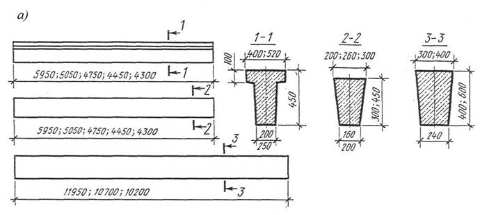
Fig. 25. Foundations of single-storey industrial buildings (a) types of foundation beams; b), c) details of foundations of the extreme row of columns; 1- sand; 2 - crushed stone preparation; 3 - Asphalt or concrete cover (blind area); 4 - waterproofing; 5 - column; 6 - slag or coarse-grained sand; 7 - reinforced concrete posts; 8 - foundation beam.
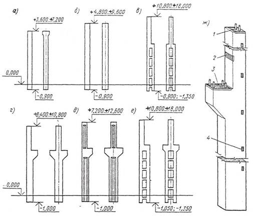
Fig. 26. The main types of reinforced concrete columns of single-storey industrial buildings. a) rectangular section for a building without bridge cranes at a step of 6 m; b) the same, with a step of 12 m; c) two-branches for buildings without bridge cranes; d) rectangular section for cranes with bridge cranes; e) the same, I-section; f) two-branches for buildings with overhead cranes; g) general view of the column; 1 - a component for fixing the bearing structure of the coating; 2, 3-the same, crane girders; 4-the same, wall panels.
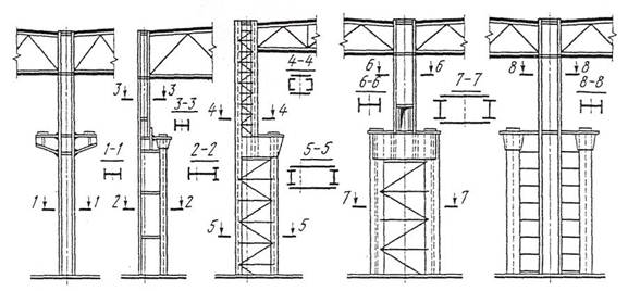
Fig. 27. The main types of steel columns
a) a constant section, b), d) of a variable section, e) a separate
600х600, 400х800, 500х500, 500х600, 500х800 mm - for rectangular ones; 400х600 and 800х800 mm - for T-bars and 400х1000, 500х1000, 500х1300, 500х1400, 500х500, 600х1400, 600х1900 and 600х2400 mm - for two-branch ones. Columns can be from several parts, which are collected on a construction site.
Columns with consoles consist of crane and crane branches. Section-crane branches are most often square or rectangular: 400x400 or 500x500mm. For the manufacture of columns used concrete classes B15, B40 and reinforcement of various classes.
The length of the columns is taken taking into account the height of the workshop and the depth of their embedment in the foundation, which can be: for columns of rectangular cross section without bridge cranes - 750 mm , for columns of rectangular and I-section with bridge cranes - 850 mm; for two-branch columns - 900-1200 mm.
The pillars provide for embedded parts (Fig. 2b, g):
1 - for fixing the bearing structures of the coating (steel sheet welded to special fittings);
2 - for fixing crane girders against tipping due to braking forces;
3 - for fixing crane beams from displacement (steel sheet with four M16 bolts);
4 - for fixing wall panels (63x5, welded to the carcass reinforcement before concreting the columns).
In addition to the main columns half-timbered columns are used for the construction of half-timbered houses. They are installed along the building with the step of the extreme columns of 12 m and the size of the wall panels of 6 m, as well as at the ends of the buildings.
Steel columns of single-storey buildings can have a constant height and variable cross-section. In turn, the columns with variable cross-section can be with the crane part of the continuous and through section (Fig. 27). Through columns are divided into columns with branches connected by ties, and the columns are separate, which consist of independently operating tent and crane branches. Columns of constant cross-section are used for the application of cranes with a carrying capacity of up to 20 tons and a building height of up to 9.6 meters.
In cases where the columns mainly work on central compression, use columns of solid cross-section. For the production of solid columns, a wide-band rolling or a welded I-beam is used, and for I-beams, I-beams, channel bars and forks can also be used.
Separate columns are arranged in buildings with heavy bridge cranes (125t and more). In the lower part of the columns, steel bases (shoes) are provided for mating with foundations. Bases to the foundations are fixed with anchor bolts, laid in the foundation during their manufacture. The lower support part of the column together with the base is covered with a layer of concrete
Columns of industrial buildings are the main bearing elements that perceive the load from coating forms, crane beams, bridge cranes, wind loads, in addition, the columns provide spatial rigidity of the building.
By appointment, the columns are extreme and medium.
By design, the columns are for buildings that do not have bridge cranes, and for buildings equipped. Columns for buildings equipped with cranes consist of two parts: crane and crane crane.
The columns are made of reinforced concrete and steel.
Reinforced concrete columns - from prestressed reinforced concrete. Apply concrete grades of 200, 300, 400 (kg / cm3). Dimensions of reinforced concrete columns depend on the width and height of the span, the pitch of the columns and the carrying capacity of overhead cranes.
Metal columns made of steel. Columns consist of a rod and a lower part - a shoe. The shoe serves to transfer the load from the column to the foundation and is fixed to it by anchor bolts. In a cross-section, the column is a combination of rolled profiles interconnected by overlays.
According to the construction of the column there are:
- constant section;
- stepped;
- separate.
If the column has a constant cross-sectional area, then the load on the column is transmitted through the console on which the crane beam is supported. In stepped columns of a variable cross-sectional area, the load from the crane beam is transferred directly to the column core.
The column of a separate type consists of two rows of supplied rods connected together, but separately perceiving the load from the tent and the crane.
Foundations for columns
In those cases where a deep foundation of foundations is needed, the columns are placed on the sub-columns, and the latter on the foundations. The foundations for columns and sub-columns are made of concrete grade 200, reinforced with steel mesh. A foundation can be supported by one, two or four columns.
The depth of foundation of the columns of the building depends on the depth of foundation of the equipment (near the columns), the distance between the column and equipment, the characteristics of the ground and the loads carried by the columns.
At the present time, there has been a tendency for designing new industrial buildings to be set in such a deepening of the columns so that in the future, if necessary, earthwork can be made without fear of breaking the strength of the building due to soil shedding.
For crane buildings, the depth of the columns is 8 m, for crane buildings 4.5 - 5 m.
Calculation of the bases for the foundations of columns, as well as for the foundations of any buildings and structures, is performed by deformations of the bases and bearing capacity of the soils. The calculation procedure was carried out in SNiP II-15-74.