The effectiveness of the functioning of ventilation systems depends on the correct selection of individual elements and equipment. Calculation of the duct area is performed in order to ensure the required multiplicity of air changes in each room, depending on its purpose. Forced and natural ventilation requires separate algorithms for design work, but it has common directions. During the determination of airflow resistance, the geometry and material of the air ducting, their total length, the kinematic scheme, and the presence of branches are taken into account. In addition, the calculation of heat losses to ensure a favorable microclimate and reduce the cost of maintaining the building in the winter period.
The calculation of the cross-sectional area is performed on the basis of data on the aerodynamic calculation of the ducts. Taking into account the received values, the following is done:
- Selection of the optimum sizes of cross-sections of air ducts taking into account the normative permissible speeds of air flow.
- Determination of the maximum pressure loss in the ventilation system, depending on the geometry, speed and features of the duct design.
Sequence of calculation of ventilation systems
1. Determination of calculated indicators of individual sections of the common system. Areas are limited to tees or process flaps, the airflow along the length of the entire section is stable. If there are branches from the site, their airflow is summed up, and the total is determined for the site. The values obtained are displayed in the axonometric diagram.
2. Selection of the main direction of the ventilation or heating system. The backbone section has the largest air flow among all those allocated during the calculations. It should be the longest of all successively located individual sections and branches. According to normative documents, the numbering of sections begins with the least loaded and continues as the air flow increases.
An example diagram of a ventilation system with a designation of branches and sections
3. The parameters of the sections of the calculated sections of the ventilation system are selected taking into account the recommended speeds in air ducts and louvred grilles. According to the state standards, the air velocity in the main pipelines is ≤ 8 m / s, in branches ≤ 5 m / s, in the louver grids ≤ 3 m / s.
In view of the existing preconditions, calculations are performed on the ventilation system.
Total pressure losses in ducts:

Calculation of rectangular ducts by loss of pressure:
R is the specific frictional loss on the airway surface;
L is the length of the duct;
n - correction factor depending on the roughness of the air ducts.
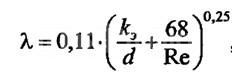
Specific pressure losses for circular sections are determined by the formula:
λ - coefficient of the hydraulic friction resistance;
d is the diameter of the duct section;
R d is the actual pressure.
To calculate the coefficient of friction resistance for a circular pipe section, the following formula is used:

During the calculations it is allowed to use tables in which, based on the above formulas, practical friction losses, dynamic pressure and air flow rates for different flow rates are determined.
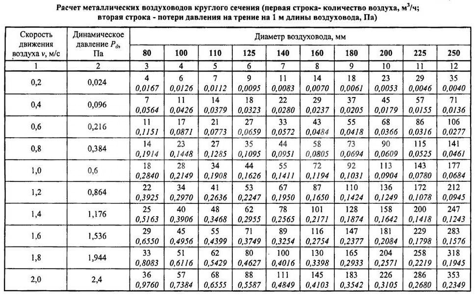
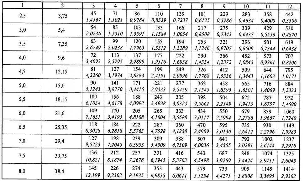


It should be borne in mind that the actual air flow rates in rectangular and circular air ducts with the same cross-sectional area are not the same even when the airflow velocity is completely equal. If the air temperature exceeds + 20 ° C, then use correction factors for friction and local resistance.
Calculation of the ventilation system consists of calculating the main highway and all branches connected to it. In this case, it is necessary to achieve a position that the speed of air movement increases constantly as it approaches the suction or discharge fan. If the airway circuit does not allow for the loss of branches, and their values do not exceed 10% of the total flow, a diagram for suppressing the excess pressure is permitted. The coefficient of resistance to the air flow of the diaphragm is calculated by the formula:

The above ductwork calculations are suitable for the following types of ventilation:
- Extractor. Used to remove from the production, commercial, sports and residential premises of exhaust air. In addition, it can have special filters for cleaning out air emitted from dust or harmful chemical compounds, can be mounted inside or outside the premises.
- Supply. The premises are supplied with prepared (heated or purified) air, can have special devices for lowering the noise level, automation of control, etc.
- Supply / exhaust. A complex of equipment and devices for supplying / removing air from premises for various purposes can have heat recovery units, which considerably reduces the costs of maintaining a favorable microclimate in the premises.
The movement of air flows along the ducts can be horizontal, vertical or angular. Taking into account the architectural features of the premises, their number and dimensions, air ducts can be mounted in several tiers in the same room.
Calculation of pipeline cross-section area
After the speed of air movement along the ducts has been determined taking into account the required multiplicity of the exchange, it is possible to calculate the air duct cross-section parameters according to the formula S = R \\ 3600v, where S is the cross-sectional area of the duct, R is the air flow rate in m 3 / hour, v is the air speed flow, 3600 - time correction factor. The cross-sectional area makes it possible to determine the diameter of a circular duct according to the formula:
![]()
If a square duct is mounted in the room, then it is calculated by the formula d e = 1.30 x ((a x b) 0.625 / (a + b) 0.25).
d e - equivalent diameter for circular duct in millimeters;
a and b are the lengths of the sides of a square or a rectangle in millimeters. To simplify the calculations, use the conversion table number 1.
Table No. 1

To calculate the equivalent diameter of oval ducts, use the formula d = 1.55 S 0.625 / P 0.2
S - cross-sectional area of the air duct of the oval duct;
P is the perimeter of the pipe.
The cross-sectional area of the oval pipe is calculated by the formula S = π × a × b / 4
S - cross-sectional area of the oval duct;
a = large diameter of the oval duct;
b = smaller diameter of the oval duct.
Selection of oval or square air ducts by the speed of air flowTo facilitate the selection of the optimal parameter, the designers calculated the finished tables. With their help, you can choose the optimal dimensions of ducts of any cross-section, depending on the frequency of air exchange in the premises. The multiplicity of the exchange is chosen taking into account the volume of the premises and the requirements of SanPin.

Calculation of the parameters of air ducts and natural ventilation systemsUnlike the forced supply / removal of air for natural ventilation, the difference in pressure between the outside and inside the premises is important. The calculation of the resistance and the choice of direction must be made in such a way as to guarantee a minimum loss of pressure of the flow.
In the calculations, the existing gravitational pressures are coordinated with the actual pressure losses in the vertical and horizontal ducts.

Classifications of raw data during the calculation of duct cross-sectionsDuring calculations it is necessary to take into account the requirements of the current SNiPa 2.04.05-91 and SNIP 41-01-2003. The calculation of ventilation systems along the diameter of the air ducts and the equipment used should ensure:
- Normalized indicators for air purity, multiplicity of exchange and microclimate indices in the premises. The capacity of the equipment to be installed is calculated. At the same time, the noise and vibration level can not exceed the established limits for buildings and premises, taking into account their purpose.
- The systems must be maintainable, during the scheduled maintenance work the technological cycle of the functioning of the enterprises should not be violated.
- In rooms with an aggressive environment, only special air ducts and equipment are provided that exclude sparking. Hot surfaces must be additionally insulated.
Norms of design conditions for determining the cross-section of air ducts
Calculation of the area of ducts should provide:
- Proper conditions for cleanliness and temperature in the rooms. For rooms with excess heat, ensure its removal, and in rooms with a lack of heat minimize the loss of warm air. At the same time, one should adhere to the economic expediency of fulfilling the above conditions.
- The speed of air movement in the premises should not worsen the comfort of staying in people's rooms. This takes into account mandatory cleaning of air in working areas. In the stream of air entering the room, the speed of motion Nx is determined by the formula Nx = Kn × n. The maximum temperature of the incoming air is determined by the formula tx = tn + D t1, and the minimum temperature by the formula tcx = tn + D t2. Where: nn, tn is the normalized airflow velocity in m / s and the air temperature at the workplace in degrees Celsius, K = 6 (the airflow rate at the outlet from the duct and indoors), D t1, D t2 is the maximum permissible deviation temperature.
- The limiting concentration of harmful to health chemicals and suspended particles in accordance with GOST 12.1.005-88. In addition, it is necessary to take into account the latest resolutions of the State Supervision.
- Parameters of outside air. Regulated in accordance with the technological features of the production process, the specific purpose of the structure and buildings. Indicators of concentration of explosive compounds and substances must meet the requirements of fire-fighting state authorities.
Installation of ventilation systems with forced air supply / removal should be done only in cases when the characteristics of natural ventilation can not provide the required parameters for cleanliness and temperature conditions in rooms or buildings have separate zones with a complete lack of natural airflow. For some rooms, the area of the air ducts is selected so that there is constant support in the rooms and the supply of outside air is excluded. This applies to pits, cellars and other premises in which there is a possibility of accumulation of harmful substances. In addition, air cooling should be present at workplaces that have a thermal radiation of more than 140 W / m 2.
Requirements for ventilation systemsIf the calculated data on ventilation systems reduce the temperature in the premises to + 12 ° C, then it is mandatory to provide for simultaneous heating. Heating systems of the appropriate power are connected to the systems to bring the temperature values up to the normed by state standards. If ventilation is installed in production buildings or in public spaces where people permanently reside, then at least two supply and two exhaust permanent units must be provided. The size of the ductwork area should provide the estimated value of the air flow. For connected or adjacent rooms it is allowed to have two exhaust systems and one inflow system or vice versa.
If the premises are to be ventilated around the clock, then it is necessary to connect the emergency equipment to the installed ductwork. Additional branches should be taken into account, and a separate calculation of the area is made for them. You can not install a redundant fan only if:
- After the failure of the ventilation system, it is possible to quickly stop the work process or take people out of the room.
- Technical parameters of emergency ventilation fully meet the requirements for cleanliness and air temperature in the premises.
General Requirements for DuctsCalculation of the final duct parameters should include the possibility of:
- Mount the fire damper vertically or horizontally.
- Installations on the interstorey sites of air closures. The design features of the devices should ensure compliance with regulatory requirements for emergency shutdown of individual branches of the ventilation system and to prevent the spread of smoke or fire throughout the building. In this case, the length of the section on which the gates are connected should not be less than two meters.
- For each floor collector, no more than five ducts can be connected. The connection node creates additional resistance to the air flow, this feature must be taken into account during the calculation of the dimensions.
- Installation of automatic fire alarm systems. If the alarm drive is mounted inside the duct, then in determining its optimum diameter, one should take into account the reduction in the effective diameter and the appearance of additional resistance to the air flow due to turbulence. The same requirements are advanced when installing check valves, preventing the flow of harmful chemical compounds from one production room to another.
Ducts of non-combustible materials should be installed for ventilation systems with suction of fire hazardous products or with a temperature of more than +80 ° C. The main transit sections of ventilation should be metal. In addition, metal ducts are installed in attic rooms, in technical rooms, in cellars and underground.
Total air losses for shaped products are determined by the formula:
![]()
Where p is the specific pressure loss per square meter of the unfolded section of the duct, ΣAi is the total unfolded area. Within the limits of one scheme for mounting the ventilation system, losses can be taken from the table.
When calculating the dimensions of ducts, in any case, engineering assistance will be required, our employees have enough knowledge to solve all technical issues.
Ventilation plays a crucial role in creating an optimal microclimate in the home. Correctly designed ventilation system ensures the removal of contaminated air, harmful gases, vapors and dust outside the premises, which affect the health of people living in a residential area. When designing ventilation systems, a huge number of calculations are made, in which many factors and variables are taken into account.
In the performance of the ventilation system, air ducts play an important role, namely their length, cross-section and shape. It is extremely important that the calculation of the cross-section of ducts is carried out correctly, since it will depend on this whether the air duct system will allow sufficient air, air flow speed and uninterrupted operation of the ventilation system as a whole. Due to the competent calculation of the air channel area, vibration and aerodynamic noise produced by air currents will be within the permissible norm.
- Apply to professionals. The calculation will be made qualitatively, but expensive.
- Make an independent calculation using the formulas for calculating the specific air losses, gravitational backwater, the cross section of the air ducts, the formula for the speed of movement of air masses in the flues, the determination of friction losses and resistance.
- Use the online calculator.
Calculation of duct cross-section
When installing a ventilation system, it is important to correctly select and determine the parameters of all elements of the system. It is necessary to find the required amount of air, pick up equipment, calculate air ducts, fittings and other components of the ventilation network. How is ventilation calculation performed? What affects their size and cross-section? Let us examine this issue in more detail.
Air ducts must be calculated from two points of view. First, the necessary cross-section and shape is selected. It is necessary to take into account the amount of air and other parameters of the network. Also, when manufacturing, the amount of material, for example, tin, is calculated for the manufacture of pipes and shaped elements. Such a calculation of the area of the ducts allows you to determine in advance the quantity and cost of the material.
Types of air ducts
To start a couple of words, we will tell both the materials and types of air ducts. This is important due to the fact that, depending on the shape of the ducts, there are specific features of its calculation and the choice of the cross-sectional area. It is also important to focus on the material, as it affects the features of the air movement and the interaction of the flow with the walls.
In short, the ducts are:
- Metal from galvanized or black steel, stainless steel.
- Flexible of aluminum or plastic film.
- Rigid plastic.
- Tissue.
According to the form, air ducts are made of round section, rectangular and oval. The most common are round and rectangular pipes.
Most of the described air ducts are made in the factory, for example, flexible plastic or fabric, and it is difficult to manufacture them on site or in a small workshop. Most of the products that need to be calculated are made of galvanized steel or stainless steel.
Of galvanized steel, both rectangular and circular air ducts are manufactured, and no particularly expensive equipment is required for production. In most cases, a bending machine and a device for making round tubes are sufficient. Apart from a small hand tool.
Calculation of the cross section of the duct
The main task that arises in the calculation of ducts is the choice of the cross-section and the shape of the product. This process takes place in the design of the system both in specialized companies and in self-manufacturing. It is necessary to calculate the diameter of the duct or the sides of the rectangle, to choose the optimum value of the cross-sectional area.
Calculation of the cross-section is carried out in two ways:
- permissible speeds;
- constant pressure loss.
The method of permissible speeds is simpler for non-specialists, so let's consider in general terms it.
Calculation of the duct cross-section by the permissible velocity method
Calculation of the ventilation duct section by the permissible velocity method is based on the normalized maximum speed. The speed is selected for each type of room and duct section, depending on the recommended values. For each type of building there are maximum permissible speeds in the main ducts and branches, above which the use of the system is difficult due to noise and strong pressure losses.
Fig. 1 (Network diagram for calculation)

In any case, before starting the calculation it is necessary to draw up a plan of the system. First, you need to calculate the required amount of air that must be supplied and removed from the room. On this calculation, further work will be based.
The very process of calculating the cross-section by the method of admissible velocities is simplified to consist of the following stages:
- A scheme of air ducts is created, on which the sections and estimated amount of air are marked, which will be transported through them. It is better to indicate on it all the grids, diffusers, section changes, turns and valves.
- According to the selected maximum speed and air quantity, the cross section of the air duct, its diameter or the size of the sides of the rectangle is calculated.
- After all system parameters are known, you can select the fan of the required capacity and head. The selection of the fan is based on the calculation of the pressure drop in the network. This is much more difficult than just picking the cross-section of the air duct in each section. This question we will consider in general terms. Since sometimes they just select a fan with a small margin.
For calculation, it is necessary to know the parameters of the maximum air speed. They are taken from reference books and normative literature. The table shows the values for some buildings and areas of the system.
Reference speed
Values are approximate, but allow to create a system with a minimum noise level.
Rice, 2 (Nomogram of a round tin duct)

How to use these values? They must be substituted into the formula or nomograms (diagrams) used for different shapes and types of ducts.
Nomograms are usually given in the normative literature or in the instruction and description of the ducts of a particular manufacturer. For example, such schemes are completed with all flexible ducts. For pipes from tin, the data can be found in the documents and on the manufacturer's website.
In principle, it is possible not to use a nomogram, but to find the required cross-sectional area based on the air speed. A square to choose the diameter or width and length of a rectangular section.
Example
Let's consider an example. The figure shows a nomogram for a circular duct of tin. The nomogram is also useful because it allows you to specify the pressure drop on the duct section at a given speed. These data will be required in the future to select a fan.
So, which air duct to choose on the network (branch) from the grid to the highway, which will pump 100 m³ / h? On the nomogram we find the intersections of a given amount of air with a maximum speed line for a branch of 4 m / s. Also near this point we find the nearest (larger) diameter. It is a pipe with a diameter of 100 mm.
In the same way we find a section for each section. All is selected. Now it remains to select the fan and calculate the air ducts and fittings (if necessary for production).
Selection of the fan
The component part of the method of permissible speeds is the calculation of pressure losses in the duct network to select the fan of the required capacity and head.
Loss of pressure on straight sections
In principle, the required performance of the fan can be determined by adding the necessary amount of air for all rooms in the building and selecting the appropriate model in the manufacturer's catalog. But the problem is that the maximum amount of air specified in the documentation for the fan, it is able to supply only without a network of air ducts. And when the pipe is connected, its performance will drop depending on the pressure drop in the network.
To do this, the documentation gives each fan a performance diagram depending on the pressure drop in the network. And how to calculate this fall? For this it is necessary to determine:
- pressure drop on flat sections of ducts;
- losses on grids, bends, tees and other shaped elements and obstacles in the network (local resistance).
The pressure losses in the duct sections are calculated according to the same nomogram. From the intersection point of the air speed line in the selected air duct and its diameter, we find the pressure loss in pascals per meter. Next, calculate the total pressure loss in a section of a certain diameter by multiplying the specific loss by the length.
For our example with a duct of 100 mm and a velocity of about 4 m / s, the pressure loss will be about 2 Pa / m.
Loss of pressure at local resistances
Calculation of pressure losses on bends, bends, tees, changes in cross-section and transitions is much more difficult than on straight sections. For this, on the same scheme shown above, all the elements that can impede movement are indicated.
Figure 3 (Some cms)

Further it is necessary for each such local resistance in the normative literature to find the coefficient of local resistance (cms c), which is denoted by the letter ζ (zetta). The loss of pressure on each such element is found by the formula:
Pm. with. = ζ × Pd
where Pd = V2 × ρ / 2 is the dynamic pressure (V is the velocity, ρ is the air density).
For example, if in a section of 100 mm diameter already considered with an air speed of 4 m / s there will be a round bend (90 degrees turn) which 0.21 (according to the table), the pressure loss on it will be
- Pm. s = 0.21 · 42 · (1.2 / 2) = 2.0 Pa.
The average density of air at a temperature of 20 degrees is 1.2 kg / m3.
Figure 4 (Example table)
On the found parameters, a fan is selected.
Calculation of material for air ducts and fittings
Calculation of the area of air ducts and shaped products is necessary for their production. It is done in order to determine the amount of material (tin) for the manufacture of the pipe section or any shaped element.
For calculation it is necessary to use only formulas from geometry. For example, for a circular air duct, we find the diameter of a circle, multiplying which by the length of the section, we get the area of the outer surface of the pipe.
For the production of 1 meter of a pipeline with a diameter of 100 mm, it is required: π · D · 1 = 3.14 · 0.1 · 1 = 0.314 m² of sheet metal. Also it is necessary to take into account from 10-15 mm of stock on connection. Also a rectangular duct is calculated.
The calculation of the shaped parts of the ducts is complicated by the fact that for him there are no definite formulas, as for a round or rectangular section. For each element it is necessary to cut and calculate the required amount of materials. This is done in the production or in the tin workshops.
The main factor affecting the performance of the ventilation system is its proper design. In order for the system to function properly, it is necessary to make a clear calculation of the area of the ducts. The correct calculation of the ducts is responsible for:
- level of generated noise;
- amount of electricity consumed;
- tightness of the system;
- unhindered passage of air with the necessary speed and in the right volumes.
Simplify the calculation process using specialized programs (calculators) or by contacting one of the relevant companies. For self-search of necessary parameters, there are calculation formulas, which, however, will be incomprehensible to a person without proper education. The most important are the calculation formulas for any engineering work related to the design of ventilation systems.
To perform calculations using formulas, you must enter the required values instead of letters and perform the calculation. The accuracy of the final result depends solely on the clarity of the initial parameters obtained during the measurement.
Finding the right values
Initially, in order to calculate the area, you need to get the information:
- on the minimum requirements for the flow of air;
- about the greatest speed of a stream of air.
- From the correct measurements and calculations depends:
- the level of vibration and air noise, the limit of which depends on the accuracy of the calculations;
- air velocity, which can become both a cause of increased energy consumption, and an increase in pressure;
- level of tightness - only with proper calculations the ventilation system will be leakproof.
During the design of the ventilation system, it is extremely important to pay attention to all possible aspects, as with this approach the system will turn out to be practical and not less durable. In addition, only properly designed ventilation can easily cope with its original tasks. In particular, it is important to pay attention to the calculations when installing the ventilation system in large production and public premises.
The value of the cross-section of the area depends on the speed of the air flow - the more it is, the faster the air moves. Also, the value of this value will greatly reduce the level of power consumption and aerodynamic noise of the system. Due to the large cross-sectional dimensions, the total cost of the ventilation system increases. In addition, such ventilation can not be installed in rooms with a suspended ceiling. The problem can be solved using rectangular air ducts, but sacrificing, at the same time, the weighty operational advantages of round products.
Ultimately, only user preferences determine which system is best to choose. If you need the greatest energy savings and a complete absence of aerodynamic noise, a square ventilation system is ideal. However, such ventilation takes up a lot of space. If in priority only the ease of installation or in a room it is impossible to install a bulky rectangular system, it is worth paying attention to products with a circular cross-section.
With due regard to the design process, you can easily achieve an ideal ventilation system.
Calculations by formulas
When performing calculations, you must follow the formula intended for these purposes:
Sc = L * 2.778 / V,
Here Sc is the area of the section; L - air flow rate (m2 / h); V - speed of air in a certain place of construction (m / s); 2.778 - fixed coefficient.
After all the required calculations, the result is the number in square centimeters.
To find out the actual area of ventilation, use the appropriate formulas:
- round products - S = Pi * D squared / 400;
- rectangular products - S = A * B / 100.
Legend, here S is the area; D is the diameter; A and B - dimensions of the duct.
Only after the completion of all calculations and re-examination of the result can you start real installation work. By this time, the entire design of the ventilation system must be completed.
Loss of pressure
Being in the air duct of the ventilation system, the air experiences some resistance. To be able to overcome it, the system must have an appropriate level of pressure. It is generally accepted that air pressure is measured in its own units - Pa.
All calculations are necessary using a specialized formula:
P = R * L + Ei * V2 * Y / 2,
Here P is the pressure; R - partial changes in the pressure level; L - total dimensions of the entire duct (length); Ei - coefficient of all possible losses (summarized); V is the air velocity in the network; Y is the density of air currents.
Familiar with all sorts of conventions that occur in formulas, perhaps with the help of special literature (reference books). In this case, the value of Ei is unique in each individual case because of the dependence on a certain type of ventilation.
Other all kinds of help can be obtained at specialized forums on the Internet. However, the opinion of each specialist is unique in its own way.
Heating device power
To determine the most suitable power of the heating device, it is necessary to take into account:
- the required temperature;
- the index of the lowest possible temperature outside the room.
Specialists assumed that the minimum temperature level inside the ventilation systems does not exceed 18 degrees Celsius. Internal temperature conditions depend exclusively on the external climate. For ordinary apartments, a heater with a power of 1-5 kW is most suitable. Public (including office) rooms require a more productive device, whose power is 5-50 kW.
To make the most accurate calculations of the required power of the heater, you can use the following formula:
P = T * L * Cv / 1000,
Here P is the power of the heating device (kW); T is the difference in the main temperatures (indoors and outside); L - efficiency of the ventilation system; Cv - heat capacity (0.336 W * h / meters square / degree Celsius).
Having made the necessary calculations, you can easily select the right air heater, which fully meets the user's preferences. In addition, the accuracy of the results will affect the subsequent operation of the ventilation system.
Shaped products
 To calculate the necessary parameters for both shaped products and the ventilation itself, it is not necessary to use formulas independently. To simplify the entire design process, engineers created specialized programs (calculators) that are capable of calculating themselves. The only thing that is required from the user is to enter the requested values.
It is up to the engineer alone to calculate the value for the fittings of fittings. However, even professionals are not able to do without special tables, values and formulas with the necessary coefficients. A person without sufficient knowledge in the relevant fields can not carry out the design independently.
When calculating the diameter of the duct, a table of equivalent diameters should be used. This table takes into account air ducts with a large cross-section, where reducing the frictional pressure is equivalent to reducing the pressure of rectangular structures. Equivalent diameters are only necessary if you need to perform the calculation of rectangular facades using tables for designs with large cross sections (round).
In both cases, a professional approach to computation is necessary. If any of the parameters do not correspond to reality, the ventilation system can not be established.
Equivalent (equivalent) value can be learned in one of three ways:
- by air consumption;
- by the speed of air flow;
- along the cross section of the duct.
Each of these values is completely associated with some parameter of the ventilation system. To define each parameter, you will need to use an individual calculation table. As a result, the value of the frictional pressure loss is obtained. If all measurements were correct, regardless of the method of calculation, the result will be completely identical. Errors in the calculations may arise due to violation of the requirements for measurements.
Additionally
More detailed information on designing (tables, formulas, reference books, etc.) can be found without problems on the Internet on various thematic forums. From the correctly selected measuring instruments, the final result (the strength of both the structure itself and its fixtures) depends entirely. It is easiest to make the required measurements with the help of special calculators and other engineering programs. In this case, you do not need to perform the calculations yourself - you just need to enter the requested numbers.
In the case of online calculators, the result will be more accurate than with manual calculations. This is due to the fact that the program itself, in the automatic mode, tends to round the result to a more accurate and understandable value.
The performance of the ventilation system depends on the correctness of its design. The most important role in this is played by the correct calculation of the area of the ducts. On it depends:
- Unobstructed movement of air flow in the right volume, its speed;
- Tightness of the system;
- Noise level;
- Electricity consumption.
In order to find out all the necessary values, you can contact the appropriate company or use special programs (they can be easily found on the Internet). However, if necessary, you can find all the necessary parameters yourself. For this, there are formulas.
Using them is quite simple. You also need to write parameters in place of the corresponding letters and find the result. Formulas help you to find the exact values, taking into account all individual factors. Usually they are used for engineering work on designing a ventilation system.
How to find the correct values
In order to calculate the cross-sectional area, we need information:
- About the minimum required air flow;
- On the maximum possible speed of air flow.
For what the correct area calculation is necessary:
- If the flow rate is higher than the set limit, this will cause a drop in pressure. These factors, in turn, will increase electricity consumption;
- Aerodynamic noise and vibration, if done correctly, will be within normal limits;
- Provide the required level of tightness.

This will also improve the efficiency of the system, help make it durable and practical. Finding the optimal network parameters is a crucial point in the design. Only in this case the ventilation system will last a long time, perfectly coping with all its functions. This is especially true for large public and industrial premises.
The larger the cross section, the lower the air speed. This will also reduce aerodynamic noise and power consumption. But there are also disadvantages: the cost of such ducts will be higher, and the construction can not always be installed in the space above the curtain ceiling. However, this is possible with rectangular products, the height of which is smaller. At the same time, round products are easier to install and have important operational advantages.
What to choose depends on your requirements, the priority of energy saving, the very features of the premises. If you want to save electricity, make noise minimal and you have the opportunity to establish a large network, choose a system of rectangular shape. If the simplicity of installation is the priority or it is difficult to install rectangular type constructions in the room, you can choose the products of circular section.
The area is calculated using the following formula:
Sc = L * 2, 778 / V
Sc here is the cross-sectional area;
L - air flow rate in meters per cube / hour;
V - speed of air flow in the duct in meters per second;
2,778 is the required ratio.

After the calculation of the area is completed, you will get the result in square centimeters.
The actual area of the air ducts will help determine the following formulas:
For round: S = Pi * D in square / 400
For rectangular: S = A * B / 100
S here is the actual cross-sectional area;
D is the diameter of the structure;
A and B are the height and width of the structures.
How to determine pressure loss
Calculation of the network resistance allows you to take into account the pressure loss. The flow of air, during movement, experiences a certain resistance. It is important to overcome this pressure. The pressure is measured in Pa.
To find out the required parameter, you need the following formula:
P = R * L + Ei * V2 * Y / 2
R here is the specific pressure reduction for friction in the network;
L - length of ducts;
Ei - coefficient of local losses in the network in the amount;
V is the air velocity in the considered section of the network;
Y is the air density.
R can be found in the corresponding directory. Ei depends on local resistance.
How to determine the optimum power of the air heater
In order to determine the optimum power of the air heater, the required air temperature and the lowest temperature outside the room are required.

The minimum temperature in the ventilation system is 18 degrees. The temperature outside the room depends on the climatic conditions. For apartments, the optimal power of the heater is usually from 1 to 5 kW, for office premises - 5-50 kW.
The exact calculation of the heater's power in the network will allow the following formula to be fulfilled:
P = T * L * Cv / 1000
P here is the power of the heater in kW;
T is the difference in the temperature of the air inside and outside the room. This value can be found in SNiP;
L - capacity of the ventilation system;
Cv - heat capacity, equal to 0.336 W * h / meter square / degree Celsius.
Additional Information
In order to know the required parameters of shaped products and the design itself, it is not necessary to perform the calculation of the parts of the ventilation network. To find all the values there are special programs. You just enter the required numbers, and you will get the result in a fraction of a second.
The values of fasteners, fittings, ducts are usually calculated by engineers involved in the design of ventilation systems. But they also apply tables that have all the required coefficients, formulas, and values.
There is also a special table of equivalent duct diameters. This table is the diameter of blowers of circular shape, in which the reduction in frictional pressure is equal to the reduction in pressure in the constructions of a rectangular shape. The equivalent diameter of the blower is required when rectangular blowers are to be calculated, and a table for round products is used.

There are three ways to know the equivalent value:
- Focusing on speed;
- Cross section;
- By consumption.
All these values are related to the width and other values of the ducts. For each of the parameters uses its own method of using tables. The final result is the value of the frictional pressure loss. Regardless of what method you used, the result is the same.
On the Internet, you can easily find the tables, programs, directories needed to calculate the area and other parameters of the structures themselves, the fastenings. The simplest thing is to use special programs. In this case, you only need to enter the desired values. The results you get are pretty accurate.